

Anti-reflection and anti-laser-damage glass and preparation method thereof
An anti-laser and anti-reflection technology, applied in the field of glass, can solve problems such as damage to optical components, and achieve the effects of low refractive index, high hardness, and stable chemical properties
- Summary
- Abstract
- Description
- Claims
- Application Information
AI Technical Summary
Problems solved by technology
Method used
Image

Examples
Embodiment 1
[0026] Embodiment 1: The preparation method of anti-reflection and anti-laser damage glass of the present invention comprises the following steps:
[0027] 1) Surface treatment of the substrate: the substrate was ultrasonically cleaned in deionized water and ethanol for 30 minutes respectively, and then dried with nitrogen;
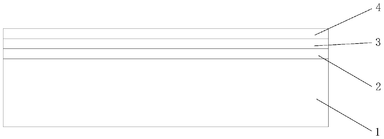
[0028] 2) Prepare the inner layer: send the substrate into the coating chamber, and use radio frequency magnetron sputtering to form SiO 2 layer, the temperature of the substrate is 25°C, the negative bias voltage is 50V, the working pressure is 0.2Pa, the substrate speed is 2rpm, the silicon target current is 2A, O 2 The flow rate is 2sccm, the argon flow rate is 5sccm, the sputtering time is 10min, the RF power is 100W, and the distance between the silicon target and the substrate is 30mm;
[0029] 3) Preparation of the first layer of the middle layer: continue RF magnetron sputtering to form SiO 2 +ZrO 2 layer, where SiO 2 with ZrO 2 The mass rati...
Embodiment 2
[0032] Embodiment 2: The preparation method of anti-reflection and anti-laser damage glass of the present invention comprises the following steps:
[0033] 1) Perform surface treatment on the substrate: ultrasonically clean the substrate in deionized water and ethanol for 30 minutes respectively, and then blow dry with nitrogen;
[0034] 2) Prepare the inner layer: send the substrate into the coating chamber, and use radio frequency magnetron sputtering to form SiO2 layer, the temperature of the substrate is 60°C, the negative bias voltage is 150V, the working pressure is 1Pa, the substrate speed is 8rpm, the silicon target current is 4A, O 2 The flow rate is 6sccm, the argon gas flow rate is 25sccm, the sputtering time is 30min, the RF power is 200W, and the distance between the silicon target and the substrate is 60mm;
[0035] 3) Preparation of the first layer of the middle layer: continue RF magnetron sputtering to form SiO 2 +ZrO 2 layer, where SiO 2 with ZrO 2 The ma...
Embodiment 3
[0038] Embodiment 3: The preparation method of anti-reflection and anti-laser damage glass of the present invention comprises the following steps:
[0039] 1) Perform surface treatment on the substrate: ultrasonically clean the substrate in deionized water and ethanol for 30 minutes respectively, and then blow dry with nitrogen;
[0040] 2) Prepare the inner layer: send the substrate into the coating chamber, and use radio frequency magnetron sputtering to form SiO 2 layer, the temperature of the substrate is 45°C, the negative bias voltage is 100V, the working pressure is 0.6Pa, the substrate speed is 5rpm, the silicon target current is 3A, O 2 The flow rate is 4sccm, the argon flow rate is 15sccm, the sputtering time is 20min, the RF power is 150W, and the distance between the silicon target and the substrate is 45mm;
[0041] 3) Preparation of the first layer of the middle layer: continue RF magnetron sputtering to form SiO 2 +ZrO 2 layer, where SiO 2 with ZrO 2 The ma...
PUM
| Property | Measurement | Unit |
|---|---|---|
| thickness | aaaaa | aaaaa |
| thickness | aaaaa | aaaaa |
| thickness | aaaaa | aaaaa |
Abstract
Description
Claims
Application Information