
Eureka
For R&D, Eureka makes reading and utilizing patents & technical documents easy.
Eureka AIR
Designed for self-driven R&D workflows. Generate viable solutions, solve complex R&D challenges, empower your innovation with AI.

Eureka Materials
Designed for material experts only. Revolutionize your material R&D, from search, analyze, to developing new materials.

TechResearch
Generate reliable direction feasibility study reports for your R&D in just a few steps.

TechSeek
Discover and master advanced knowledge NOW. Basics, ideas, possibilities, all at once.

TechMind
As an expert in R&D Theories, TechMind can generates customized viable solutions instantly.

TechRisk
Analyze your overall solution with one click, know your potential R&D risks in advance.

TechMonitor
Get weekly tech updates, stay abreast of the latest tech innovations and key insights.
Gene chip with high-flux detection
A gene chip and high-throughput technology, applied in chemical libraries, combinatorial chemistry, organic compound libraries, etc., can solve problems such as easy interference detection signals, blurred hybridization signals, and reduced signal-to-noise ratio, so as to improve hybridization efficiency and accuracy Improvement of performance and accuracy
- Summary
- Abstract
- Description
- Claims
- Application Information
AI Technical Summary
Problems solved by technology
Method used
Image

Examples
Embodiment 1
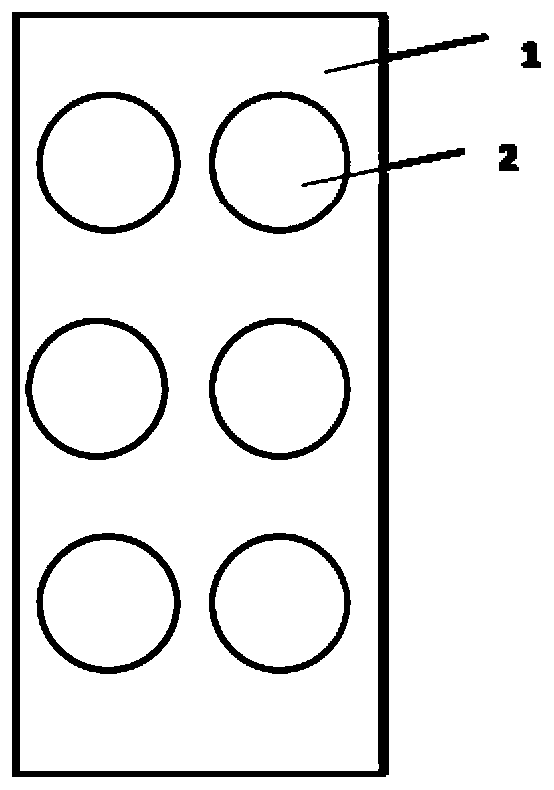
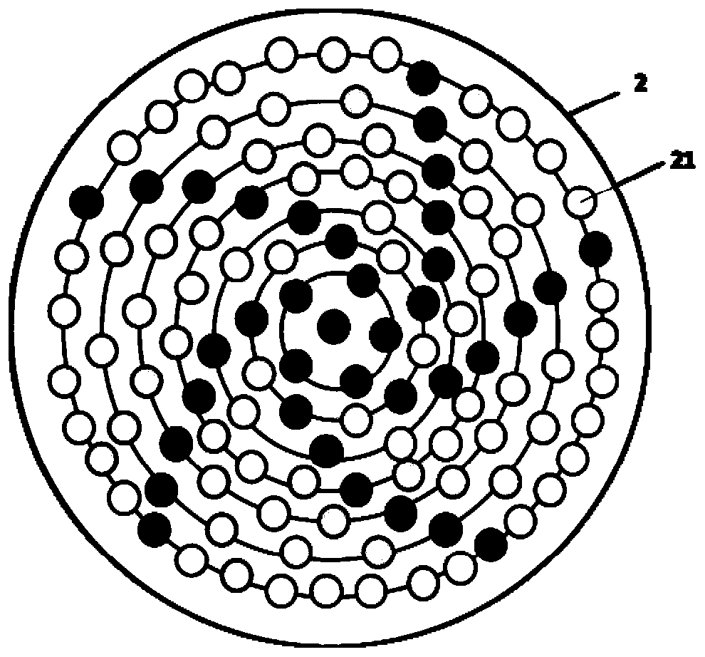
[0031] A gene chip for high-throughput detection, including a solid-phase carrier layer and 6 gene chip areas arranged on the solid-phase carrier layer. The gene chip area is provided with a probe array, and the probe array is an array of concentric circles, forming a concentric array. The probe points on two adjacent rings of the circular array are arranged alternately.
[0032] The probe array on the above-mentioned gene chip is a concentric circle array, and the probe points of two adjacent circles are arranged in a staggered manner, which can avoid mutual interference between two adjacent points during the probe synthesis process and affect the final signal recognition , thus significantly improving the accuracy of genetic testing.
Embodiment 2
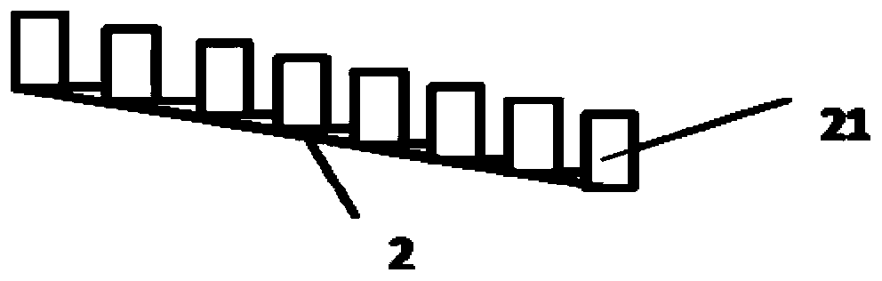
[0034] It is basically the same as in Example 1, except that the gene chip area includes a basement membrane layer and a carrying layer connected up and down, wherein the carrying layer is a nitrocellulose layer, the basement membrane layer is connected to the solid phase carrier layer, and the probe The array is set on the bearing layer, two adjacent rings forming a concentric array on the bearing layer, the height of the inner ring is higher than the height of the outer ring, and any two adjacent rings forming a concentric array on the bearing layer The height difference is equal, and the height difference between the innermost ring and the outermost ring forming the concentric circle array on the bearing layer is 1 / 3 of the radius of the concentric circle array. On the one hand, this design can make the reaction solution flow to the outer circle in the process of hybridization to improve the hybridization efficiency; on the other hand, it can make the eluent flow to the oute...
Embodiment 3
[0036] It is basically the same as Example 2, except that the height difference between the innermost ring and the outermost ring forming the concentric circle array on the carrying layer is 1 / 5 of the radius of the concentric circle array, and the carrying layer is a glass slide layer .
PUM
 Abstract
Description
Claims
Application Information
 - R&D Engineer
- R&D Manager
- IP Professional
- Industry Leading Data Capabilities
- Powerful AI technology
- Patent DNA Extraction
Browse by: Latest US Patents, China's latest patents, Technical Efficacy Thesaurus, Application Domain, Technology Topic, Popular Technical Reports.
© 2024 PatSnap. All rights reserved.Legal|Privacy policy|Modern Slavery Act Transparency Statement|Sitemap|About US| Contact US: help@patsnap.com