Plasma surface treatment equipment for granular and powdery materials

A technology of plasma and powder materials, which is applied in the field of plasma technology, can solve the problems that powder or metal powder cannot be processed, gas cannot be excited, and the processing capacity is small. good sex effect

Pending Publication Date: 2019-06-11
深圳市奥普斯等离子体科技有限公司
View PDF2 Cites 5 Cited by
  • Summary
  • Abstract
  • Description
  • Claims
  • Application Information

AI Technical Summary

Problems solved by technology

[0006] Chinese patent CN201120333715 discloses a low-temperature plasma treatment device for the surface of granular materials. The device uses a single drum to treat the surface of larger granular materials, but the device can only process granular materials, not powder or metal powder. On the one hand, the metal powder is easy to enter the vacuum pipeline system; on the other hand, the metal powder is easy to stick to the surface of the cylinder, forming an electric field shield, so that the gas in the vacuum chamber cannot be excited into plasma
[0007] Chinese patent CN201110101689 discloses a low-temperature plasma surface treatment method and device for powder materials. Electric field, generate plasma and surface modification reaction; but the processing capacity is small, and similarly, it cannot meet the processing requirements for metal powder

Method used


Image

  • Plasma surface treatment equipment for granular and powdery materials
  • Plasma surface treatment equipment for granular and powdery materials
  • Plasma surface treatment equipment for granular and powdery materials

Examples


Embodiment 1

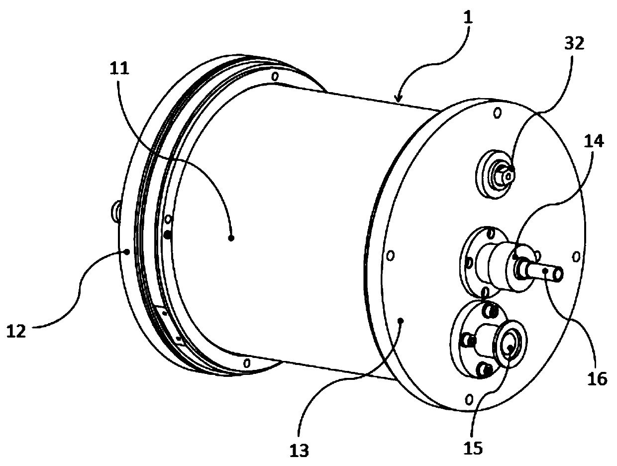
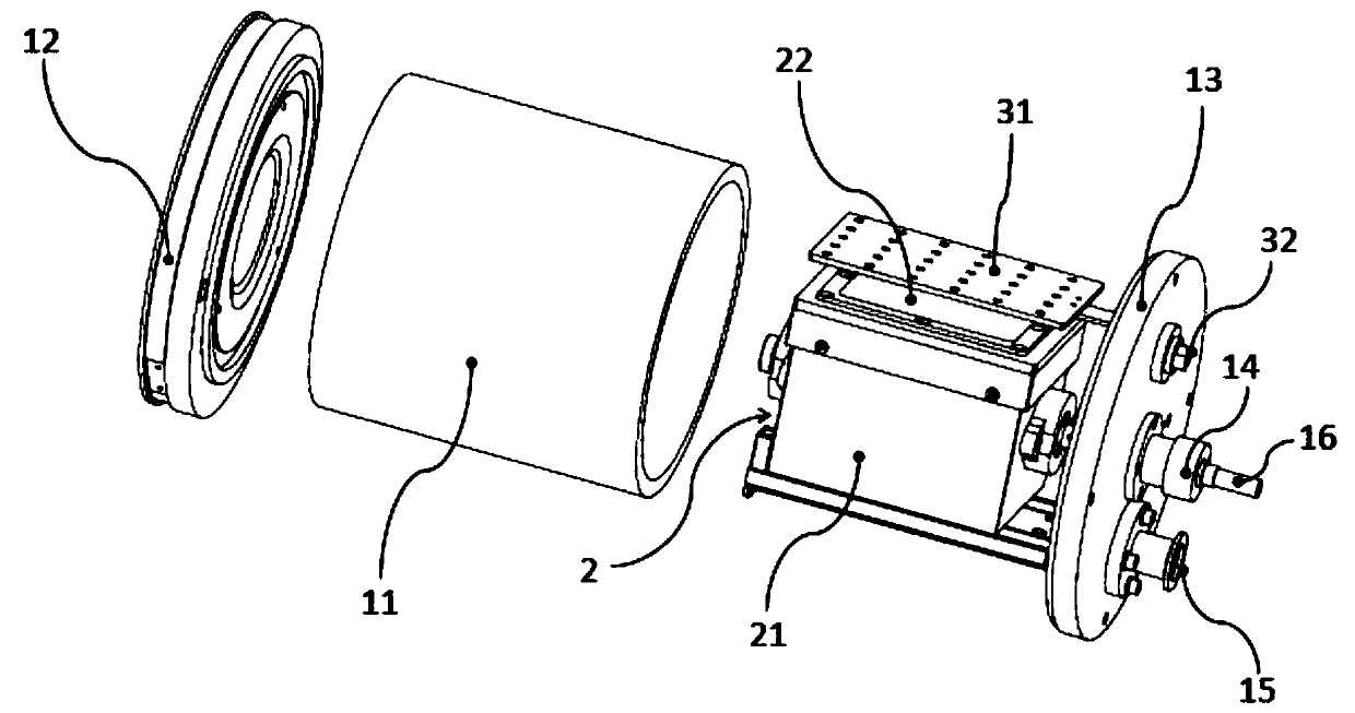
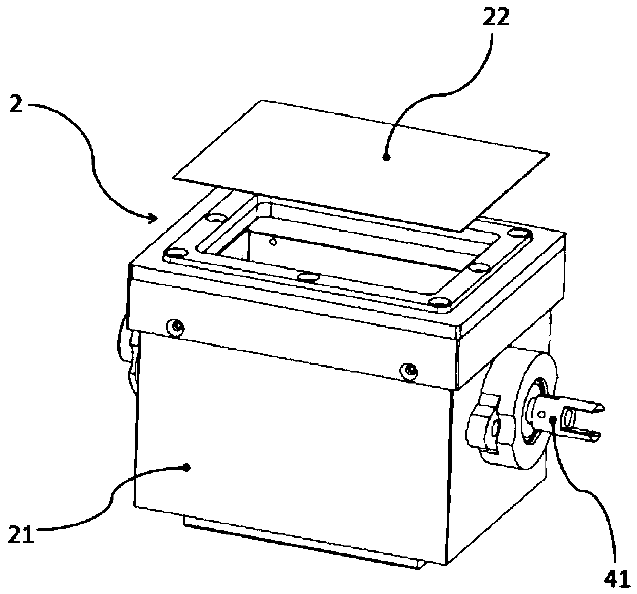
[0025] as 1- Figure 4 As shown, a plasma surface treatment equipment for particles and powder materials includes a vacuum outer chamber 1, a vacuum inner chamber 2, a particle stirring mechanism 4 and a plasma generator, and the vacuum inner chamber 2 is set in the vacuum outer chamber 1 , the particle stirring mechanism 4 is located in the vacuum inner cavity 2, and the plasma generator is located on the particle stirring mechanism 4; the right side of the vacuum outer cavity 1 is provided with a vacuum suction port 15 and an air inlet 14, and the The vacuum inner chamber 2 comprises a reaction chamber 21 and a filter screen 22, the top of the reaction chamber 21 is open, the filter screen 22 is arranged on the top of the reaction chamber 21, and the air inlet 13 communicates with the right side of the vacuum inner chamber 2; The plasma generator includes an electrode set 31 and a plasma generating power source, and the electrode set 31 is arranged above the filter plate 22 ...

Embodiment 2

[0032] as 1- Figure 4 As shown, a plasma surface treatment equipment for particles and powder materials includes a vacuum outer chamber 1, a vacuum inner chamber 2, a particle stirring mechanism 4 and a plasma generator, and the vacuum inner chamber 2 is set in the vacuum outer chamber 1 , the particle stirring mechanism 4 is located in the vacuum inner cavity 2, and the plasma generator is located on the particle stirring mechanism 4; the right side of the vacuum outer cavity 1 is provided with a vacuum suction port 15 and an air inlet 14, and the The vacuum inner chamber 2 comprises a reaction chamber 21 and a filter screen 22, the top of the reaction chamber 21 is open, the filter screen 22 is arranged on the top of the reaction chamber 21, and the air inlet 13 communicates with the right side of the vacuum inner chamber 2; The plasma generator includes an electrode set 31 and a plasma generating power source, and the electrode set 31 is arranged above the filter plate 22 ...


PUM


Abstract

The invention discloses plasma surface treatment equipment for granular and powdery materials, comprising a vacuum outer cavity, a vacuum inner cavity, a particle stirring mechanism and a plasma generator, wherein the vacuum inner cavity is disposed in the vacuum outer cavity, the particle stirring mechanism is disposed in the vacuum inner cavity; the right side of the vacuum outer cavity is provided with a vacuum suction port and an air inlet, the vacuum inner cavity includes a reaction chamber and a filter mesh plate, and the air inlet port communicates with the right side of the vacuum inner cavity; and the plasma generator includes an electrode group and a plasma generating power source. The particle stirring mechanism stirs particles, and the treatment is uniform; at the same time, the vacuum outer cavity and the vacuum inner cavity are arranged, the sealing is good, and the treated particles are prevented from overflowing; the filter mesh plate is arranged in the vacuum inner cavity, and the particle size of treatable particles and powder is wide; functional treatment, such as hydrophilic treatment, hydrophobic treatment and coating wrapping, is carried out on the surfaces ofparticles by exciting different types of plasma.

Description

technical field [0001] The invention relates to the application field of plasma technology, in particular to a plasma surface treatment device for particles and powder materials. Background technique [0002] Material surface modification technology is one of the commonly used material preparation technologies at present. Its basic principle refers to the use of physical, chemical, mechanical and other methods to treat the material surface or interface, and purposely change the physical and chemical properties of the material surface, such as Surface energy, surface wettability, electrical properties, adsorption and reaction characteristics, surface structure and functional groups, etc., ultimately meet the needs of new materials, new processes and new technologies. For granular and powder materials, surface modification methods are more limited than for other shaped materials. [0003] At present, the methods for surface treatment of particles and powder materials are usua...

Claims


Application Information

Patent Timeline
Patent Type & Authority Applications(China)
IPC IPC(8): B01J19/08B01J3/03
Inventor 欧阳军朱威
Owner 深圳市奥普斯等离子体科技有限公司
Why Eureka
Try Eureka