Water mobile-type slurry treatment equipment and treatment process

A treatment device and mobile technology, applied in the direction of water/sludge/sewage treatment, sludge treatment, water/sewage multi-stage treatment, etc., can solve the problem of transportation costs, high comprehensive labor costs, inconvenience at the construction site, centrifugal dehydration Problems such as high energy consumption can solve the problem of mud treatment, the effect of weight reduction is remarkable, and the effect of reducing transportation costs

Inactive Publication Date: 2019-06-11
SHANGHAI WATERWAY ENG DESIGN & CONSULTING
View PDF5 Cites 2 Cited by
  • Summary
  • Abstract
  • Description
  • Claims
  • Application Information

AI Technical Summary

Problems solved by technology

[0003] At present, there are mainly the following mud processing methods, but all of them have relatively large disadvantages: 1. The tank truck (mud truck) is transported abroad. This method is to directly lift the mud generated on site into the mud truck through the mud pump. The mud is transported by mud truck to the free space on the outskirts of the city for natural drying, but the comprehensive cost of transportation, labor, management and other costs required by this method is relatively high, the comprehensive cost per cubic meter is high, and the consumption area is different. 2. On-site sedimentation and drying. This method needs to build a sedimentation tank on the construction site, discharge the generated mud into it, and carry out natural sedimentation and drying. Sometimes some flocculants are added for flocculation treatment before proceeding. Precipitation and drying, but this method needs to occupy a large area of ​​land, the treatment period is long, and it is easy to cause inconvenience to the construction site; 3. Centrifugal dehydration, a centrifuge can be used to dehydrate the construction mud, but due to the repeated stirring of the mud water during piling construction, the mud water The binding force is enhanced, especially for silty mud. It is difficult to quickly separate the mud and water by centrifugal force. At the same time, the energy consumption of centrifugal dehydration is large and the processing capacity is relatively low.

Method used


Image

  • Water mobile-type slurry treatment equipment and treatment process
  • Water mobile-type slurry treatment equipment and treatment process
  • Water mobile-type slurry treatment equipment and treatment process

Examples


Embodiment 1

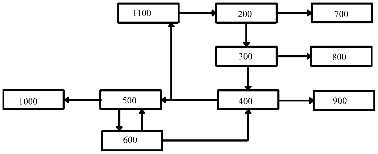
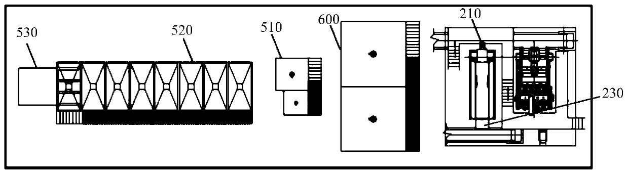
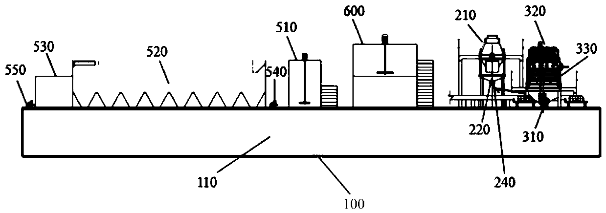
[0034] figure 1 It is a process flow diagram of the present invention. figure 2 It is a schematic top view of the first buoyancy platform of the present invention. image 3 It is a schematic plan view of the first buoyancy platform of the present invention. Figure 4 It is a schematic top view of the second buoyancy platform of the invention. Figure 5 It is a schematic plan view of the second buoyancy platform of the invention.

[0035] Such as Figure 1 to Figure 5 As shown, a water mobile mud treatment device includes: buoyancy platform 100, impurity removal system 200, sand removal system 300, dehydration system 400, tail water treatment system 500, drug dispensing system 600, solid residue recovery device 700, waste residue receiving device 800, the mud cake receiving device 900 and the tail water standard discharge device 1000, the impurity removal system 200, the sand removal system 300, the dehydration system 400, the tail water treatment system 500 and the dispen...


PUM


Abstract

The invention provides water mobile-type slurry-processing equipment. The equipment comprises a buoyancy platform, an impurity removing system, a sand removing system, a dewatering system, a tail water treatment system, a dispensing system, a solid residue recovery device, a waste-residue receiving device, a mud cake receiving device and a tail water up-to-standard discharge device; and the impurity removing system, the sand removing system, the dewatering system, the tail water treatment system and the dispensing system are connected with the upper part of the buoyancy platform, an outlet ofthe impurity removing system is connected with the solid residue recovery device, an outlet of the sand removing system is connected with an inlet of the waste-residue receiving device and an inlet ofthe dewatering system, an outlet of the dispensing system is connected with the inlet of the dewatering system, an outlet of the dewatering system is connected with an inlet of the mud cake receivingdevice and an inlet of the tail water treatment system, and an outlet of the tail water treatment system is connected with the dispensing system and the tail water up-to-standard discharge device. Compared with a conventional technology, the equipment provided by the invention realizes reduction and stabilization treatment of slurry, reduces subsequent slurry transportation costs, and effectivelysolves a current slurry treatment difficult problem in cities.

Description

technical field [0001] The invention relates to the technical field of shield tunneling / construction / river mud reduction and stabilization treatment, in particular to a water mobile mud treatment device and a treatment process. Background technique [0002] At present, the mud in the city mainly comes from construction engineering mud and river silt. With the continuous acceleration of urbanization and the rapid advancement of water environment management, the amount of mud produced is also increasing. Each cubic of natural soil can produce 3-4 cubic mud. Therefore, each project usually produces tens of thousands or even millions of cubic meters of mud that needs to be shipped out. Due to the high moisture content of the mud, most of the actual transported mud is water when the mud is directly transported outside, and the transportation efficiency is low, which greatly increases the urban traffic burden and causes energy waste. If it is not handled properly, it will not on...

Claims


Application Information

Patent Timeline
IPC IPC(8): C02F9/04C02F11/122
Inventor 朱治赵天彪赵东华季岚张双福郭生昌陈海英刘冰
Owner SHANGHAI WATERWAY ENG DESIGN & CONSULTING
Why Eureka
Try Eureka