Ocean energy power-generation device

A power generation device and marine technology, applied in ocean energy power generation, hydroelectric power generation, safety devices, etc., can solve problems such as inability to generate power continuously, high power generation cost, erosion of power generation equipment, etc., to increase the utilization rate of ocean energy and water flow , The effect of increasing power generation efficiency

Inactive Publication Date: 2019-06-11
金华市秸和环保技术咨询有限公司
View PDF0 Cites 1 Cited by
  • Summary
  • Abstract
  • Description
  • Claims
  • Application Information

AI Technical Summary

Problems solved by technology

At present, there are ways to generate electricity through tidal interception, including allowing seawater to enter the reservoir during high tide, using the tidal difference between the reservoir and the sea surface to drive hydroelectric generators to generate electricity during ebb tide, or using the special design of the reservoir and the function of the sluice to control the tide between high tide and ebb tide. However, the above-mentioned methods have the disadvantage of being unable to continuously generate electricity, and the energy conversion rate is low, the unit power generation cost is high, and the capital consumption is large, which limits its popularization and application to a certain extent.
Moreover, the power generation equipment is eroded by seawater all the year round and is easily damaged, resulting in a short service life

Method used


Image

  • Ocean energy power-generation device
  • Ocean energy power-generation device
  • Ocean energy power-generation device

Examples


Embodiment 1

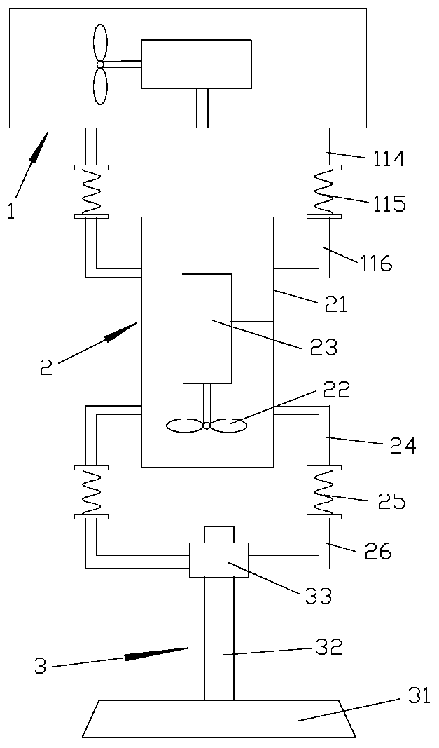
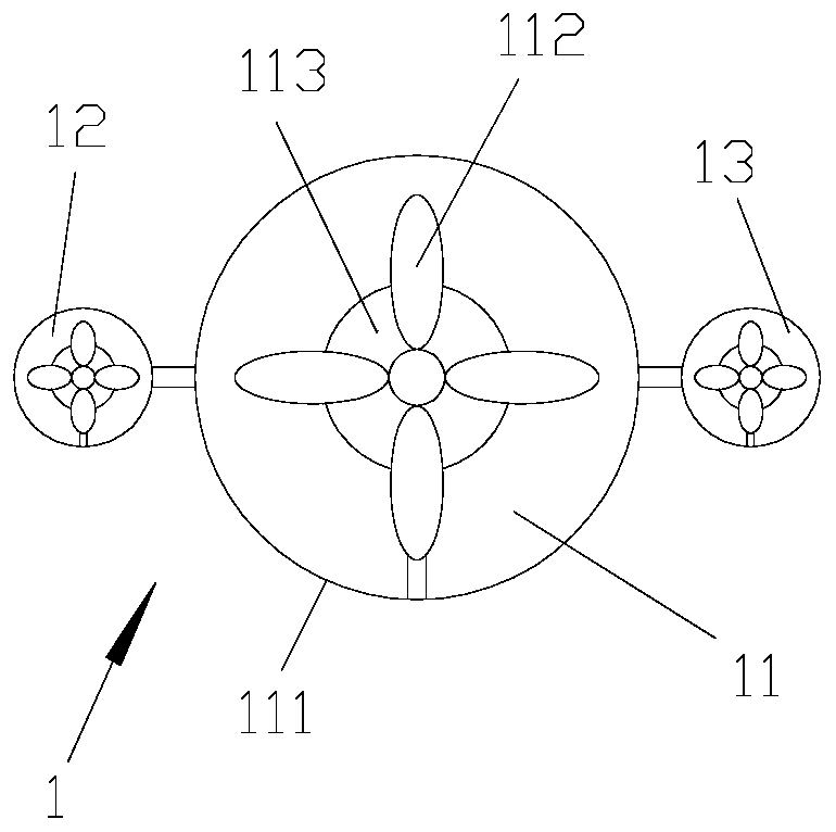
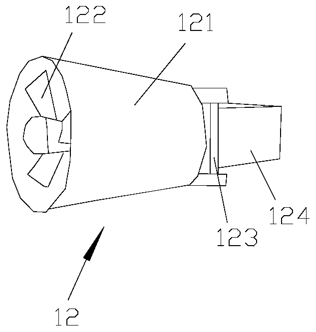
[0020] refer to Figure 1-3 As shown, a kind of ocean energy generating device comprises a water current generating device 1 floating on the sea surface, a suspension generating device 2 connected to the water current generating device 1 suspended in water, and a fixing device 3 connected to the suspension generating device 2; The water flow power generation device 1 includes a central water flow power generation device 11, and a first turbine generator 12 and a second turbine generator 13 arranged on both sides of the water flow power generation device 11, the first turbine generator 12 and the second turbine generator 13, the central water flow power generation device 11 includes a horizontal floating tube 111, a first power generation propeller 112 arranged inside the floating tube 111, and a first generator 113 connected to the first power generation propeller 112; the central water flow power generation The bottom of the device 11 is provided with a first fixed column 114...

Embodiment 2

[0031] refer to Figure 1-3As shown, a kind of ocean energy generating device comprises a water current generating device 1 floating on the sea surface, a suspension generating device 2 connected to the water current generating device 1 suspended in water, and a fixing device 3 connected to the suspension generating device 2; The water flow power generation device 1 includes a central water flow power generation device 11, and a first turbine generator 12 and a second turbine generator 13 arranged on both sides of the water flow power generation device 11, the first turbine generator 12 and the second turbine generator 13, the central water flow power generation device 11 includes a horizontal floating tube 111, a first power generation propeller 112 arranged inside the floating tube 111, and a first generator 113 connected to the first power generation propeller 112; the central water flow power generation The bottom of the device 11 is provided with a first fixed column 114,...

Embodiment 3

[0042] refer to Figure 1-3 As shown, a kind of ocean energy generating device comprises a water current generating device 1 floating on the sea surface, a suspension generating device 2 connected to the water current generating device 1 suspended in water, and a fixing device 3 connected to the suspension generating device 2; The water flow power generation device 1 includes a central water flow power generation device 11, and a first turbine generator 12 and a second turbine generator 13 arranged on both sides of the water flow power generation device 11, the first turbine generator 12 and the second turbine generator 13, the central water flow power generation device 11 includes a horizontal floating tube 111, a first power generation propeller 112 arranged inside the floating tube 111, and a first generator 113 connected to the first power generation propeller 112; the central water flow power generation The bottom of the device 11 is provided with a first fixed column 114...


PUM


Abstract

The invention discloses an ocean energy power-generation device. By combining a water flow power-generation device with a suspended power-generation device, the ocean energy utilization rate is increased, the power-generation efficiency is improved, the direction of the water flow power-generation device is controlled through an empennage arranged at the tail of a turbine generator, and thus the water flow utilization rate of the water flow power-generation device is increased; the ocean energy power-generation device is coated with coating, thus the service life of the ocean energy power-generation device is prolonged, the effect of the coating is embodied in that vinyltriethoxysilane and pelargonic acid vanillylamide can be contained in a base body through methyl methacrylate, the methylmethacrylate is slowly hydrolyzed in seawater to release the pelargonic acid vanillylamide, while the vinyltriethoxysilane generates a hydrophilic group, and thus antifouling property is further achieved; and insoluble polymer with a three-way net structure can be formed by diphenol propane type epoxy resin and trimethyl hexamethylene diamine, an interpenetrating network structure can be formed in the polymer with the three-way net structure by diphenol propane type epoxy resin and acrylic resin to achieve the anti-corrosion effect.

Description

technical field [0001] The invention relates to an ocean energy generating device. Background technique [0002] Due to the continuous improvement of modern living standards, electricity consumption is also growing rapidly. However, with the consumption of non-renewable resources such as oil and coal mines, people gradually consider how to use the energy on the ocean to generate electricity. At present, there are ways to generate electricity through tidal interception, including allowing seawater to enter the reservoir during high tide, using the tidal difference between the reservoir and the sea surface to drive hydroelectric generators to generate electricity during ebb tide, or using the special design of the reservoir and the function of the sluice to control the tide between high tide and ebb tide. However, the above-mentioned methods have the disadvantages of being unable to generate electricity continuously, and the energy conversion rate is low, the unit power gener...

Claims


Application Information

Patent Timeline
Patent Type & Authority Applications(China)
IPC IPC(8): F03B13/00F03B11/00F03B13/26F03B15/00C09D4/02C09D4/06C09D5/16C09D7/61C09D7/63C09D7/65
CPCY02E10/20Y02E10/30
Inventor 罗志诚
Owner 金华市秸和环保技术咨询有限公司
Why Eureka
Try Eureka