Pulsating heat pipe heat dissipating type high-power ultrasonic transducer
An ultrasonic transducer and pulsating heat pipe technology, applied in the field of ultrasonic transducers, can solve problems such as demand, complex cooling system, small heat exchange area, etc., and achieve the effect of solving high working temperature, solving technical problems and having broad application prospects.
- Summary
- Abstract
- Description
- Claims
- Application Information
AI Technical Summary
Problems solved by technology
Method used
Image

Examples
Embodiment 1
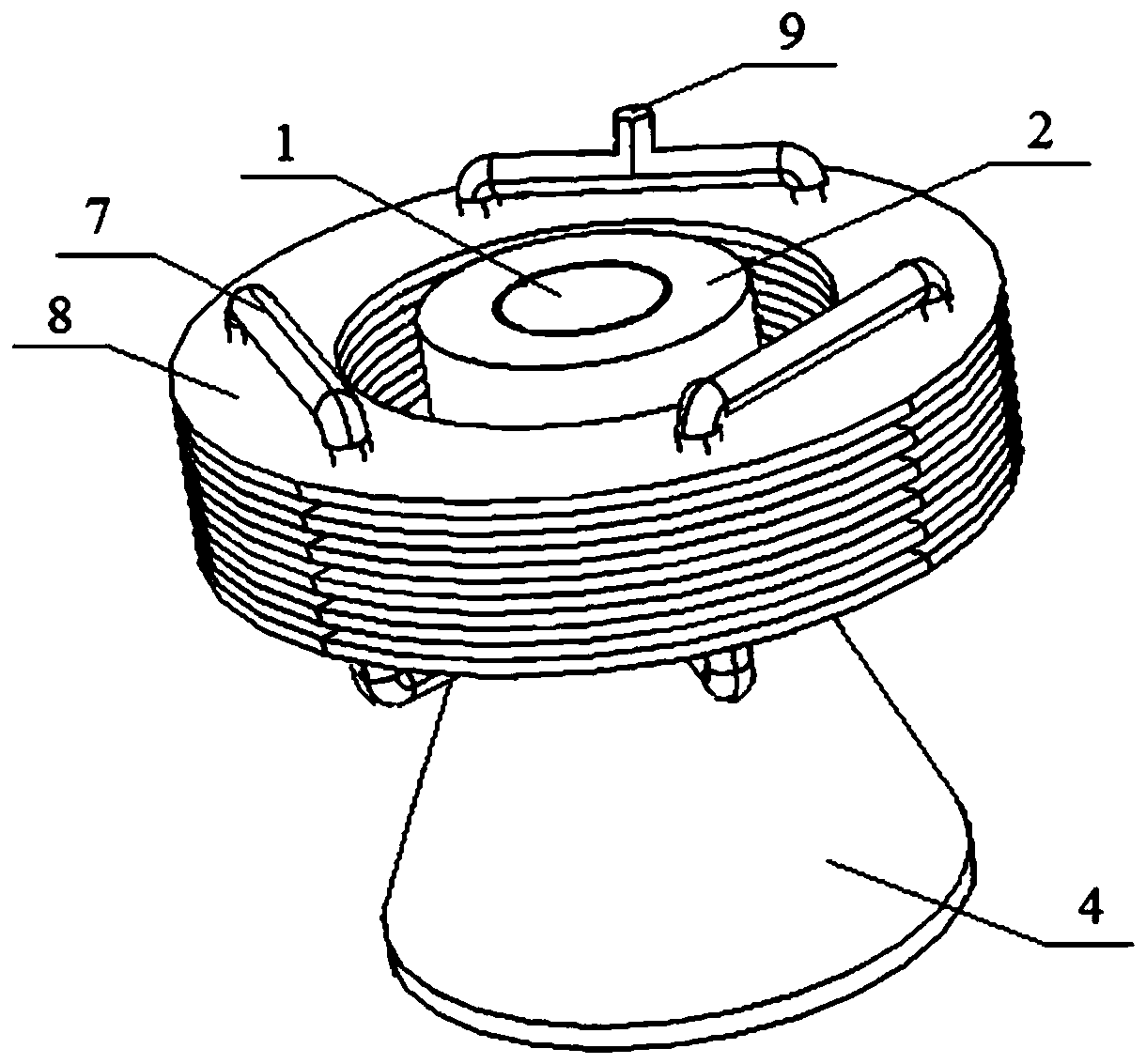
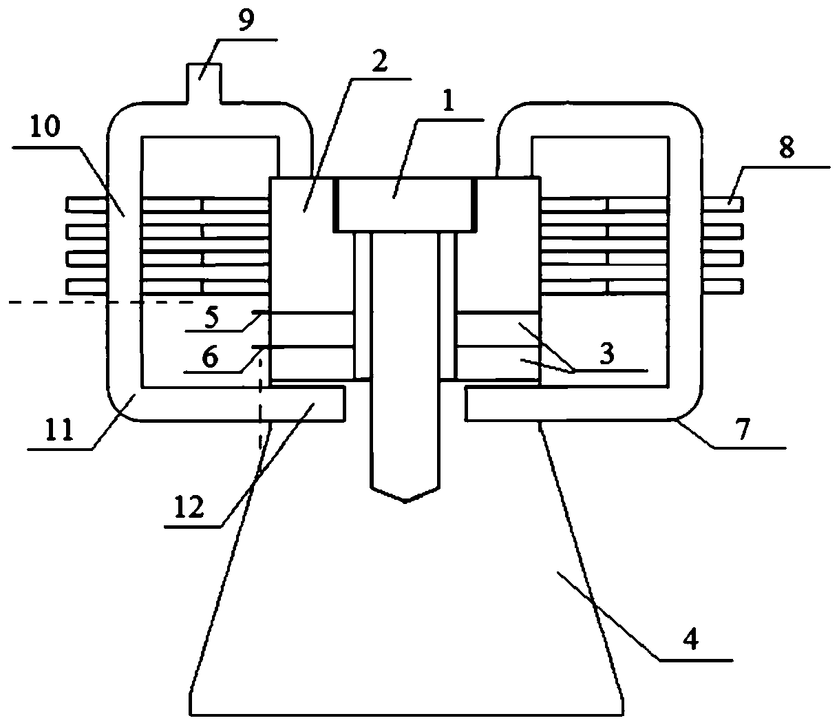
[0026] Such as figure 1 , figure 2 As shown, a preferred embodiment of the present invention includes a stress bolt 1, a cylindrical rear cover plate 2, a piezoelectric ceramic element 3, a conical front cover plate 4 with a series of holes in the radial direction, a negative electrode lead 5, a positive electrode Lead wire 6, pulsating heat pipe 7, multiple sets of heat conduction fins 8, liquid filling pipe 9, condensation section 10, heat insulation section 11 and evaporation section 12.
[0027] The cylindrical rear cover 2, the piezoelectric ceramic element 3 and the conical front cover 4 pierced with a series of holes in the radial direction are closely connected by the stress bolt 1, and processed into a cylindrical piezoelectric ultrasonic transducer, two adjacent The positive side of the piezoelectric ceramic element 3 is opposite, and a thin copper sheet is sandwiched in the middle as the positive lead end of the piezoelectric ultrasonic transducer; The upper end ...
Embodiment 2
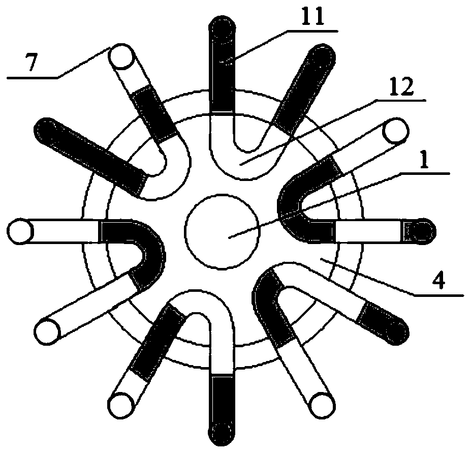
[0034] Based on the first embodiment, the pulsating heat pipe 7 in the second embodiment is in the shape of an angular tube.
PUM
| Property | Measurement | Unit |
|---|---|---|
| Diameter | aaaaa | aaaaa |
| Inclination | aaaaa | aaaaa |
Abstract
Description
Claims
Application Information
 - Generate Ideas
- Intellectual Property
- Life Sciences
- Materials
- Tech Scout
- Unparalleled Data Quality
- Higher Quality Content
- 60% Fewer Hallucinations
Browse by: Latest US Patents, China's latest patents, Technical Efficacy Thesaurus, Application Domain, Technology Topic, Popular Technical Reports.
© 2025 PatSnap. All rights reserved.Legal|Privacy policy|Modern Slavery Act Transparency Statement|Sitemap|About US| Contact US: help@patsnap.com