Polluted water source treatment equipment and treatment method thereof

A water source and equipment technology, applied in water/sewage treatment, water/sludge/sewage treatment, added material water/sewage treatment, etc., can solve the problems of farmers' loss, aquatic animal death, long effective period, etc., to achieve filtration better effect

Inactive Publication Date: 2019-06-14
廖斌
View PDF4 Cites 3 Cited by
  • Summary
  • Abstract
  • Description
  • Claims
  • Application Information

AI Technical Summary

Problems solved by technology

[0004] The traditional treatment method is to control the source of the pollution source. This treatment method takes a long time to take effect. Usually, after it takes effect, the aquatic animals in the water body have died, causing heavy losses to the farmers.

Method used


Image

  • Polluted water source treatment equipment and treatment method thereof
  • Polluted water source treatment equipment and treatment method thereof
  • Polluted water source treatment equipment and treatment method thereof

Examples


Embodiment 1

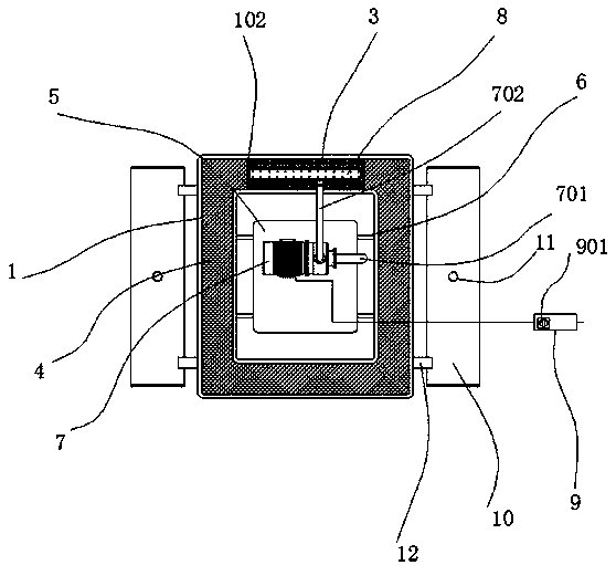
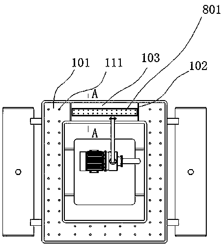
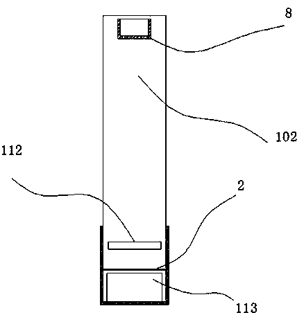
[0039] refer to figure 1 , figure 2 , image 3 with Figure 4 The shown a polluted water source treatment equipment includes a frame 1 welded by stainless steel plates, the thickness of the frame 1 is 2mm, and a cavity 101 for accommodating sewage is formed inside the frame 1, the cavity 101 The bottom position of the bottom is vertically penetrated with a drainage hole 111, and the diameter of the drainage hole is 8mm. Two vertical plates 102 are welded in the cavity 101, and a first cavity is formed between the two vertical plates 102. 103, a grid mesh 2 is welded between the two vertical plates 102, the mesh mesh is made of stainless steel, the wire diameter is 1mm, and the mesh size is 1mm×1mm. Activated carbon particles 3 are provided with an overflow port 112 at the side of the vertical plate 102 at a position 4 cm above the activated carbon particles 3, and the overflow port 112 is located in the cavity 101. When the water seepage capacity of the activated carbon part...

Embodiment 2

[0042] refer to Figure 5 As shown, the filter cotton is laid with 2 layers, and the thickness of each layer of filter cotton is 12mm.

[0043] Medical stone particles 13 are sandwiched between two adjacent layers of the filter cotton 2 , and the laying thickness of the medical stone particles 13 is 2 cm.

[0044] The filter cotton is glass fiber filter cotton.

Embodiment 3

[0046] refer to Image 6 with Figure 7 As shown, a motor 511 is vertically arranged above the supporting plate 5, a first switch 902 for controlling the opening / closing of the motor 511 is provided on the switch box 9, and the lower end of the motor 511 is equipped with The rotating shaft 512, the rotating shaft 512 extends downwards through the supporting plate 5 and extends into the water, the impeller 513 is installed on the rotating shaft 512, and the impeller only needs to be able to drive the water body; the above structure mainly realizes active oxygenation, The impeller is driven by the start of the motor, and the impeller drives the water body to rotate, thereby increasing the oxygen content in the water.


PUM

PropertyMeasurementUnit
thicknessaaaaaaaaaa
depthaaaaaaaaaa
depthaaaaaaaaaa

Abstract

The invention discloses polluted water source treatment equipment and a treatment method thereof. The polluted water source treatment equipment comprises a frame welded by stainless steel plates, an accommodating cavity for accommodating waste water is formed in the frame, a drain hole is formed in the bottom of the accommodating cavity in a vertically penetrating mode, two vertical plates are welded into the accommodating cavity, a first accommodating cavity is formed between the two vertical plates, a grating mesh is welded between the two vertical plates, activated carbon particles are supported on the upper part of the grating mesh, overfall gaps are formed in the side faces, on the position of 3-5cm on the upper parts of the activated carbon particles, of the vertical plates, the overfall gaps are formed in the accommodating cavity, when the water penetration ability of the activated carbon particles is insufficient, water accumulates in the first accommodating cavity, and overflows into the accommodating cavity through the overfall gaps. The polluted water source treatment equipment can float on water, oxygen can further be increased into water while water quality purification is conducted, and aquatic animals are prevented from dying due to hypoxia.

Description

technical field [0001] The invention relates to equipment and a treatment method for polluted water sources. Background technique [0002] Cyanobacteria do not have organelles such as chloroplast, mitochondria, Golgi apparatus, centrosome, endoplasmic reticulum and vacuole, and the only organelle is ribosome. Contains chlorophyll a, no chlorophyll b, contains several kinds of lutein and carotene, and also contains phycobilin (a general term for phycoerythrin, phycocyanin and allophycocyanin). Generally speaking, where the amount of chlorophyll a and phycocyanin is large, the cells are mostly blue-green. Similarly, there are also a few species that contain more phycoerythrin from cyanobacteria that broke out in Dianchi Lake in Kunming, and the algae are mostly red. For example, a cyanobacterium that was born in the Red Sea is called Trichophyton red sea, because it contains a lot of phycoerythrin. The algae are red and multiply quickly, so the sea water is also red, and the...

Claims


Application Information

Patent Timeline
Patent Type & Authority Applications(China)
IPC IPC(8): C02F1/00C02F1/68E02B15/10
Inventor 廖斌邓承山
Owner 廖斌
Why Eureka
Try Eureka