
A flue gas waste heat utilization and its automatic pollutant control system

A flue gas waste heat and flue gas technology, applied in the direction of indirect heat exchangers, lighting and heating equipment, separation methods, etc., can solve the problems of high toxicity, unsatisfactory operation conditions, wet electrostatic precipitator operation and high investment costs, and achieve absorption Increased thermal area, realizing intelligence and accuracy, and realizing the effect of intelligence

Active Publication Date: 2020-04-28
SHANXI WENLONG COAL MINE ENG DESIGN
View PDF14 Cites 0 Cited by
  • Summary
  • Abstract
  • Description
  • Claims
  • Application Information

AI Technical Summary

Problems solved by technology

[0004] Electrostatic precipitator + wet electrostatic precipitator technology is an important technical route to achieve ultra-low emission standards, but wet electrostatic precipitator operation and investment costs are high
Another technical route to achieve ultra-low emissions is to optimize the wet desulfurization device for efficient and coordinated removal of particulate matter. This technology needs to meet the dust concentration at the outlet of the front-end electrostatic precipitator ≤ 20mg / m 3 Even ≤10mg / m 3 , it is difficult to meet the current operating conditions of electrostatic precipitators in power plants
In addition, the emissions from coal-fired power plants will also produce a certain concentration of organic pollutants, such as alicyclic hydrocarbons, straight-chain hydrocarbons, benzene series, and polycyclic aromatic hydrocarbons. The removal of pollutants is an important research field for environmental safety.

Method used


Image

  • A flue gas waste heat utilization and its automatic pollutant control system
  • A flue gas waste heat utilization and its automatic pollutant control system
  • A flue gas waste heat utilization and its automatic pollutant control system

Examples


Embodiment Construction

[0044] The specific embodiments of the present invention will be described in detail below in conjunction with the accompanying drawings.

[0045] In this article, if there is no special explanation, when it comes to formulas, " / " means division, and "×" and "*" mean multiplication.

[0046] The specific embodiments of the present invention will be described in detail below in conjunction with the accompanying drawings.

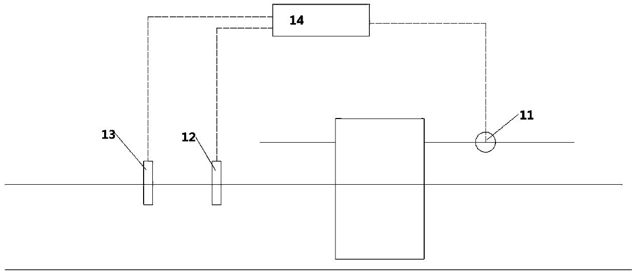
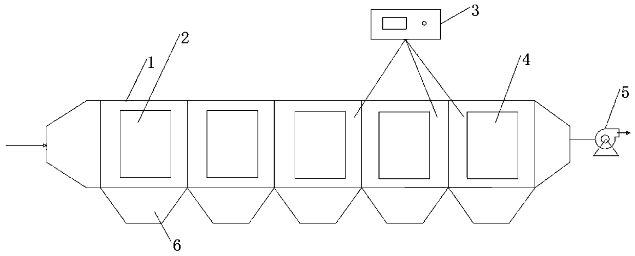
[0047] Such as figure 1 As shown, a flue gas waste heat utilization system includes a heat pipe 10, a flue gas pipe 106, and an air channel 105. The evaporation end of the heat pipe 10 is arranged in the flue gas pipe 106, and the condensation end is arranged in the air channel 105. The inlet pipe of the air channel 105 is provided with a fan 11 , and the frequency change of the fan is used to control the flow of air entering the air channel 105 . The flue gas pipeline is provided with a temperature sensor 12 and a flow sensor 13 for measuring the temperatu...


PUM


Abstract

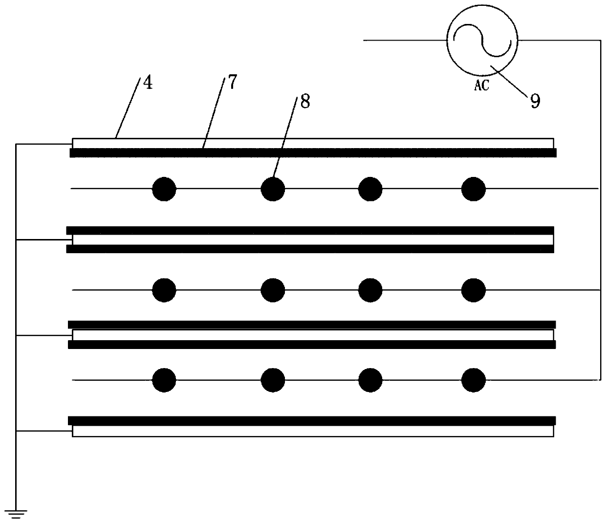
The invention provides a flue gas waste heat utilization system. The flue gas waste heat utilization system includes a heat pipe, a flue gas pipeline and an air passage, the flue gas pipeline is internally provided with a flow sensor, the flow sensor is use for detecting the flow V of flue gas, a pm2.5 detector is arranged on an inlet section of an electrostatic / ultrasonic coupling dust removal section, and the pm2.5 detector is used for detecting the pm2.5 concentration N2 on the inlet position; the pm2.5 detector is in data connection with a central control unit, and the control unit automatically adjusts the power of an ultrasonic generator according to detected data of the pm2.5 concentration N2 and the flow V. The invention provides the waste heat utilization system with a novel structure and an intelligent processing device of the waste heat utilization system, the electric field intensity can be comprehensively controlled according to the pm2.5 concentration N2 and the flow V, the intellectualization of the system is realized, and waste heat utilization is improved.

Description

technical field [0001] The invention relates to the fields of heat pipe waste heat recovery, flue gas dust removal and organic matter removal, in particular to a system for recovering flue gas waste heat by using heat pipes. Background technique [0002] Heat pipe technology is a heat transfer element called "heat pipe" invented by George Grover of Los Alamos National Laboratory in the United States in 1963. It makes full use of the principle of heat conduction and phase change medium. The rapid heat transfer properties of the heat pipe quickly transfer the heat of the heating object to the heat source, and its thermal conductivity exceeds that of any known metal. Compared with the most commonly used shell-and-tube heat exchanger in coal-fired flue gas waste heat recovery, the heat pipe heat exchanger has the advantages of high heat transfer efficiency, compact structure, small pressure loss, and is beneficial to control dew point corrosion. There is more potential in waste...

Claims


Application Information

Patent Timeline
Patent Type & Authority Patents(China)
IPC IPC(8): F23J15/02F28D21/00B01D53/86
Inventor 王逸隆刘喜梅崔林邴栋常景彩
Owner SHANXI WENLONG COAL MINE ENG DESIGN
Learn More