Wireless charging high-frequency power supply

A technology of wireless charging and high-frequency power supply, applied in charging stations, battery circuit devices, electric vehicle charging technology, etc. Interference ability, strong anti-interference ability, the effect of increasing stability

Inactive Publication Date: 2019-06-14
TAIYUAN UNIV OF TECH
View PDF9 Cites 1 Cited by
  • Summary
  • Abstract
  • Description
  • Claims
  • Application Information

AI Technical Summary

Problems solved by technology

[0005] For the existing high-frequency power supply for wireless charging, He Mu Nan proposed a wireless charging system for electric vehicles based on high-frequency switches in the article "Design and Production of High-Frequency Power Supply for Electric Vehicle Wireless Charging System Controlled by DSP". The composition of the power electronic converter, the main circuit includes EMC filter, rectifier and filter circuit, chopper circuit, high-frequency inverter circuit and other parts, the control circuit includes DSP, drive circuit, conditioning circuit, etc., and the digital signal processor DSP is used to send out The chopper circuit and the inverter circuit trigger the pulse signal, sample the voltage and current at the output of the chopper circuit, input the sampled signal to the DSP for processing, perform overvoltage and overcurrent protection, and perform PI adjustment to improve the stability of the output voltage. However, the power supply cannot monitor the output voltage and output frequency in real time, so that the staff cannot grasp the operating status of the power supply in real time, which is not conducive to the adjustment of the working status of the power supply and the analysis of the faults that occur during the operation of the power supply. At the same time, it cannot achieve convenience. output frequency adjustment; when the structure of the wireless power transmission coil changes, it will cause the problem that the power supply cannot effectively transmit electric energy to the load in a resonant manner, and it is difficult to adapt to the requirements for output frequency adjustment of the power supply when the output coil structure changes; Jiang Xiudao In the article "Research on Intelligent Charging System for Electric Vehicles", an electric vehicle charger is proposed. During operation, the 220V / 380V AC voltage is converted into DC power through rectification and filtering, and then converted into high-frequency AC power through an inverter circuit, and then coupled. The mechanism obtains alternating current, and then supplies it to the subsequent stage circuit. The charging process of the system is controlled by the single-chip microcomputer, and the voltage and current during the charging process are monitored through the single-chip microcomputer. The keypad can adjust the duty cycle, and then adjust the output voltage. The LCD screen It can also display the charging current and charging voltage, but the system cannot adjust the inverter frequency of the inverter circuit. When the wireless transmission structure changes, it will also bring power that cannot be effectively transmitted to the load through the coil wirelessly through resonance. problem, which brings great inconvenience to the inverter output frequency adjustment
[0006] The above two charging power supplies are used in the charging of electric vehicles. However, the first kind of power supply cannot monitor the output power, power and frequency, and cannot enable the staff to intuitively grasp the output status of the power supply, and it is difficult to adjust the charging process of the power supply; the second This kind of power supply cannot adjust the output frequency, and cannot meet the requirements for adjusting the resonance frequency change when the structure of the output coil of the power supply changes. It has poor adaptability to the coil and has great limitations.

Method used


Image

  • Wireless charging high-frequency power supply
  • Wireless charging high-frequency power supply
  • Wireless charging high-frequency power supply

Examples


Embodiment Construction

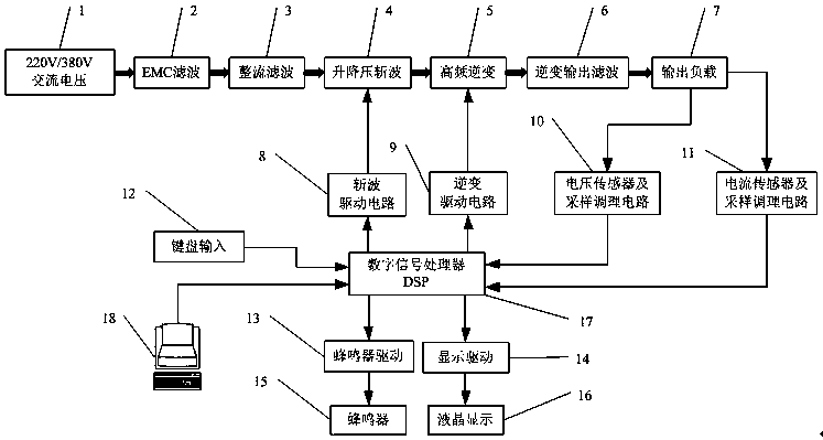
[0029]The purpose of the present invention is to design a wireless charging high-frequency power supply to solve the problem of inconvenient control of the output voltage and output AC frequency of the power supply during wireless charging of electric vehicles. The function of alarming during abnormal working conditions, for the convenience of understanding, the specific implementation will be further described below in conjunction with the accompanying drawings.

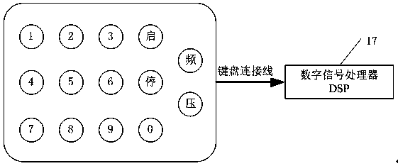
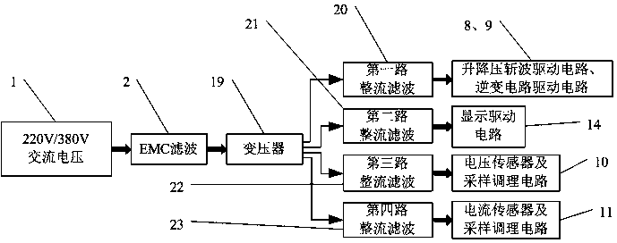
[0030] as attached figure 1 , attached figure 2 And attached image 3 A structural schematic diagram of the wireless charging high-frequency power supply, which includes a 220V / 380V AC voltage 1, an EMC filter 2, a rectification filter circuit 3, a buck-boost chopper circuit 4, a high-frequency inverter circuit 5, and an inverter output filter Circuit 6, output load 7, chopping drive circuit 8, inverter drive circuit 9, voltage sampling and conditioning circuit 10, current sampling and conditioning circuit 11, ke...


PUM


Abstract

The invention discloses a wireless charging high-frequency power supply. The wireless charging high-frequency power supply is characterized in that state detection and program control and loading areachieved on a digital signal processor (DSP) by an upper computer, a program of processing and sampling a voltage and current signal and keyboard input processing of the DSP is loaded to the DSP, a liquid crystal display frequency f, a voltage effective value U and a current effective I are output by combining the DSP, and real-time monitoring and debugging is performed on running of the loaded program in the DSP by the upper computer. By the wireless charging high-frequency power supply, the control and the observation of the power supply are improved, the wireless charging high-frequency power supply is high in operation performance and interference resistance, and actual application under an electric vehicle wireless charging occasion is facilitated.

Description

technical field [0001] The invention relates to a wireless charging power supply, in particular to a wireless charging high-frequency power supply using a digital signal processor DSP. Background technique [0002] In the electric vehicle wireless charging system, the wireless transmission power supply converts the 380V / 50Hz AC power into dozens of kHz or even 100 kHz high-frequency AC power and transmits it to the wireless charging system, manages the charging process of the electric vehicle, and grasps the working status of the high-frequency power supply in real time , which plays an important role in controlling the working conditions of the wireless charging system. [0003] During wireless charging of electric vehicles, a series of circuit structures are involved in the process of converting 50Hz AC power into high-frequency AC power by the high-frequency power supply. During wireless charging, the power supply outputs higher-frequency AC power, which can effectively i...

Claims


Application Information

Patent Timeline
Patent Type & Authority Applications(China)
IPC IPC(8): H02J7/02H02J7/04H02J50/12H02J5/00B60L53/122
CPCY02T10/72Y02T10/7072Y02T10/70Y02T90/14
Inventor 田慕琴吝伶艳刘文瑞许春雨张文杰
Owner TAIYUAN UNIV OF TECH
Why Eureka
Try Eureka