
Method for carrying out local UV varnishing on printed product

A partial and printed technology, applied in the printing field, can solve problems such as warping, peeling, inability to fix the flexographic plate well, and inaccurate registration, etc., and achieve the effects of reducing the viscosity of the system, improving the quality of glazing, and fast curing speed

Inactive Publication Date: 2019-06-18
SHANGHAI PUDONG HUANGGONG PRINTING
View PDF5 Cites 2 Cited by
  • Summary
  • Abstract
  • Description
  • Claims
  • Application Information

AI Technical Summary

Problems solved by technology

At present, a flexible resin plate (flexo plate) or a blanket is often used to apply UV varnish to the printed matter to complete the local UV glazing of the printed matter. The plate is pasted on the cylinder, and the flexographic plate cannot be fixed well. After the equipment runs for a period of time, the periphery of the printing plate will be lifted and peeled off, resulting in irregular edges of the glazing pattern, greatly reducing the yield, and the cost of the flexible plate is high. ;When using blanket varnishing, since most of the ordinary blanket will be removed, the blanket has poor stability, poor durability, and is easily damaged, resulting in inaccurate registration and other problems; in addition, the commonly used UV coating Varnish generally uses aliphatic urethane acrylate as the prepolymer monomer, and urethane acrylate has a high viscosity, which will reduce the fluidity of the varnish, affect the glazing effect of the varnish on the surface of the printed matter, and reduce the UV varnish. Adhesion and gloss on the surface of printed matter, and often need to add a large amount of reactive diluent monomer

Method used


Image

  • Method for carrying out local UV varnishing on printed product
  • Method for carrying out local UV varnishing on printed product
  • Method for carrying out local UV varnishing on printed product

Examples

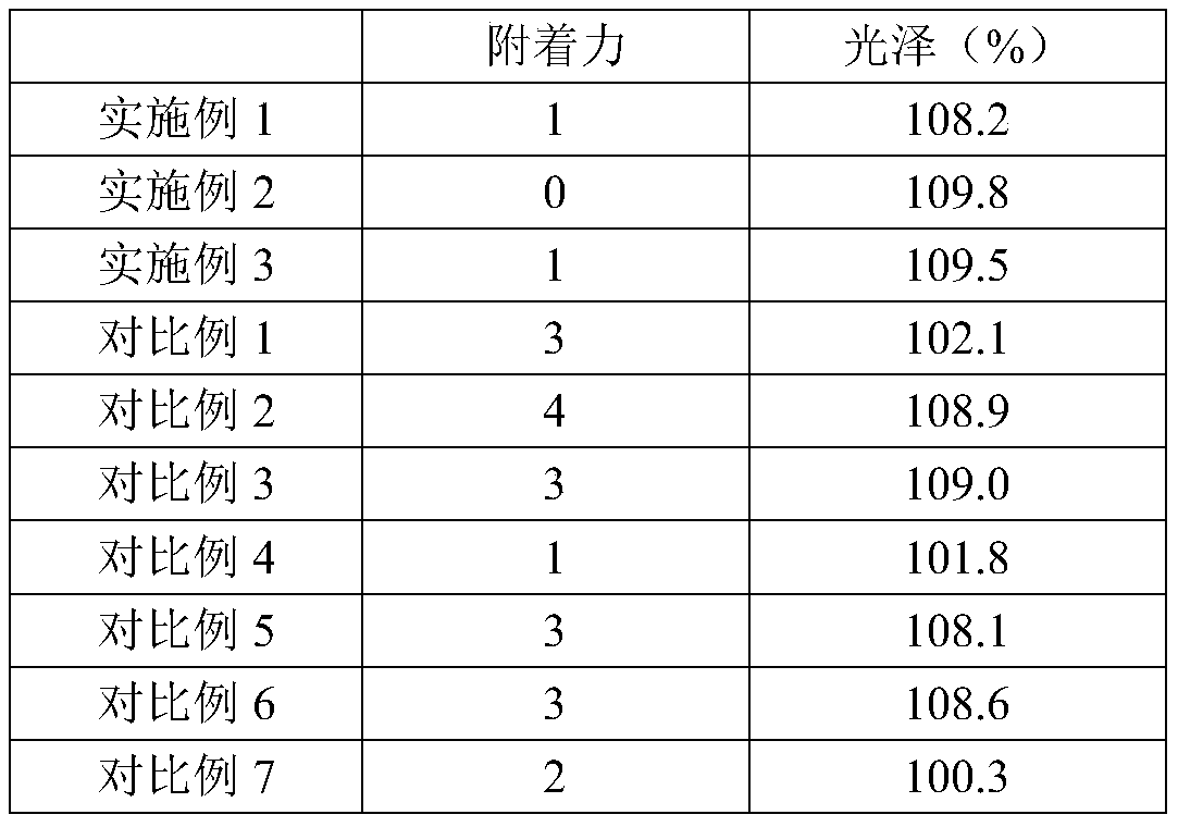

Embodiment 1~3

[0032] A method for partially UV glazing a printed matter, the steps of which are:

[0033] (1) Make a die-cut plate according to the area where the printed matter (coated paper printed matter) needs to be partially glazed, install it on the die-cutting machine, and adjust the pressure of the die-cutting machine to carry out the coating on the five-layer structure. Die-cutting to cut off the area corresponding to the non-varnished part of the printed matter, leaving the glazed area, wherein only the upper three layers of the blanket are cut through during die-cutting, and the lower two layers remain intact;

[0034] (2) Install the cut glazing blanket on the plate cylinder of the local glazing machine;

[0035] (3) Weigh hyperbranched urethane acrylate according to the quality shown in Table 1 (made by the method described in the following documents, the same below: Qian Ting, Xie Hui, Huang Li, Jin Aihong. Synthesis and curing of hyperbranched urethane acrylate Film properti...


PUM


Abstract

The invention discloses a method for carrying out local UV varnishing on a printed product, and belongs to the technical field of printing. The method comprises the following steps that firstly, a diecutting plate is manufactured according to the range, needing local varnishing, of the printed product, and then is installed on the die-cutting machine, the pressure of the die-cutting machine is adjusted to perform die-cutting on varnishing rubber cloth composed of five-layer structure so as to cut off the area corresponding to the non-varnishing part in the printed product, only the varnishingarea is left, during die cutting, only top three layers of the rubber cloth are die-cut, and the bottom two layers are kept complete; then, the cut varnishing rubber cloth is installed on a printingplate roller of a local varnishing machine; then the local varnishing machine is started, the varnishing rubber cloth is used for coating the area, where needs to be locally varnished, of the printedproduct with UV varnishing oil; and finally, a UV light curing instrument is used for curing the varnished printed product. The method is simple, and the varnishing quality of the printed product canbe improved.

Description

technical field [0001] The invention relates to a method for performing partial UV glazing on printed products, which belongs to the technical field of printing. Background technique [0002] Glazing is a post-press process and one of the surface finishing techniques for printed matter. In layman's terms, glazing is to apply a layer of colorless transparent paint on the surface of printed matter, and after leveling, drying and calendering, a thin and uniform transparent bright layer can be formed on the surface of printed matter. Glazing can not only increase the surface smoothness of printed matter, make the printed product more glossy, but also protect the printed graphics, so it is widely used in packaging and decoration, book covers, picture albums, trademarks, advertisements, calendars , large-scale decoration, posters and other printed matter surface finishing processing. As an extension of the printing process and an important means of finishing printed matter, glaz...

Claims


Application Information

Patent Timeline
Patent Type & Authority Applications(China)
IPC IPC(8): B41F23/08C09D175/14C09D163/10
Inventor 蒋约军张敦周庄苏苏庄向阳焦艳辉
Owner SHANGHAI PUDONG HUANGGONG PRINTING
Learn More