
A vacuum coating machine

A technology of vacuum coating machine and vacuum gauge, applied in the field of coating machine, can solve the problems of unreasonable cooperation mechanism of diffusion pump and mechanical pump, inability to understand and control the vacuum state of the cover body, and the coating operation of coating parts is not continuous enough, so as to shorten the preheating time. Time, increase coating effect, good sealing effect

Active Publication Date: 2020-12-22
南阳清水科技有限公司
View PDF6 Cites 1 Cited by
  • Summary
  • Abstract
  • Description
  • Claims
  • Application Information

AI Technical Summary

Problems solved by technology

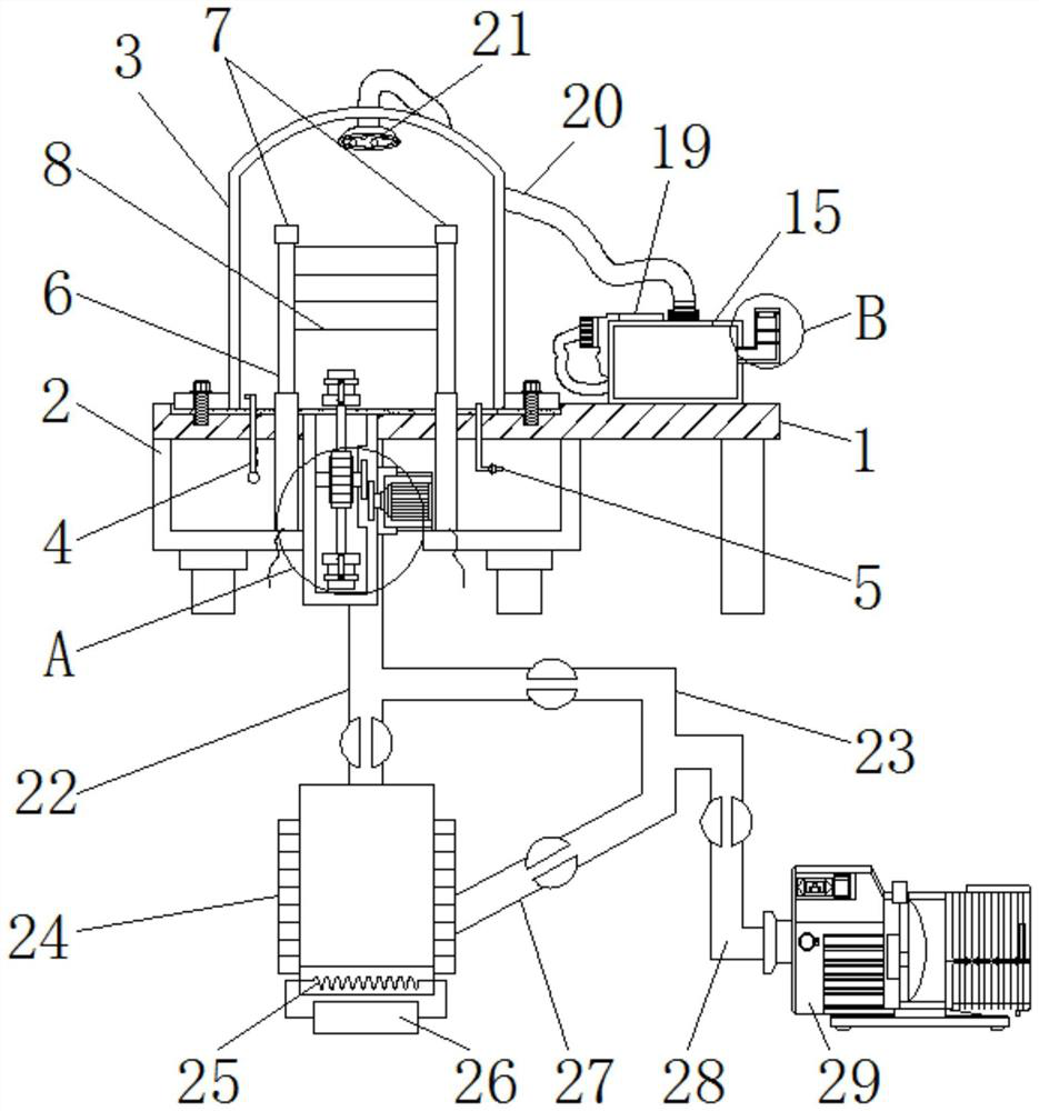
[0004] The purpose of the present invention is to provide a vacuum coating machine to solve the problem of being unable to understand and control the vacuum state in the cover body proposed in the above-mentioned background technology, and there is no cleaning device for the cover body; Coating, the efficiency is low, and the cover needs to be opened repeatedly, which affects the vacuum environment; the sealing of the device is prone to problems, and it is inconvenient to install and disassemble. The coordination mechanism between the diffusion pump and the mechanical pump is not reasonable enough, which affects the coating effect.

Method used


Image

  • A vacuum coating machine
  • A vacuum coating machine
  • A vacuum coating machine

Examples


Embodiment Construction

[0027] The following will clearly and completely describe the technical solutions in the embodiments of the present invention with reference to the accompanying drawings in the embodiments of the present invention. Obviously, the described embodiments are only some, not all, embodiments of the present invention. Based on the embodiments of the present invention, all other embodiments obtained by persons of ordinary skill in the art without making creative efforts belong to the protection scope of the present invention.

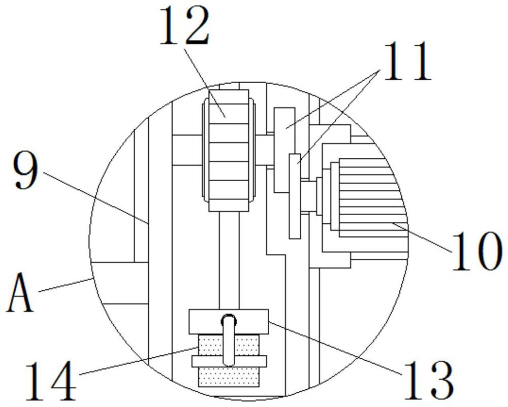
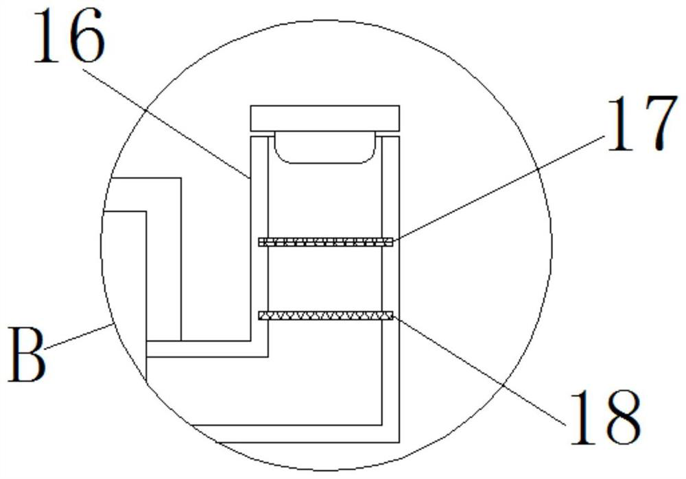
[0028] see Figure 1-6, the present invention provides a technical solution: a vacuum coating machine, including a bottom plate 1, a bracket 2, a cover body 3, a vacuum gauge 4, an air release valve 5, an electric telescopic rod 6, an evaporation electrode 7, a metal to be plated 8, a frame Body 9, motor 10, movable group 11, fixed disc 12, clamping structure 13, plating piece 14, liquid storage tank 15, material inlet 16, first filter screen 17, second filter...


PUM


Abstract

The invention discloses a vacuum coating machine. The vacuum coating machine comprises a bottom plate, a diffusion pump and a mechanical pump, wherein supports are fixedly arranged on the left side and the right side of the lower end surface of the bottom plate, a vacuum meter is arranged on the left side of the interior of a cover body, a vent valve is arranged on the right side of the interior of the cover body, electric telescopic rods are arranged on the left side and the right side of the interior of the cover body, the outer surfaces of the upper ends of the electric telescopic rods arefixedly connected with to-be-plated metals at equal intervals, frame bodies are arranged on the inner sides of the electric telescopic rods, motors are fixedly arranged on the right side surfaces of the frame bodies, a fixed disc is arranged on a linkage structure, and a liquid storage tank is fixedly arranged on the right side of the upper surface of the bottom plate. According to the vacuum coating machine, the vacuum state in the cover body can be known and controlled through the vacuum meter, moreover, a cleaning device for the cover body is arranged, so that the coating efficiency is high, the cover body is not required to be repeatedly opened, so that the sealing performance of the machine is good, moreover, assembly and disassembly are convenient, and the design of the cooperative mechanism between the diffusion pump and the mechanical pump is reasonable.

Description

technical field [0001] The invention relates to the technical field related to coating machines, in particular to a vacuum coating machine. Background technique [0002] There are various types of vacuum coating machines, because they adopt different coating principles, including vacuum ion evaporation, magnetron sputtering, MBE molecular beam epitaxy, PLD laser sputtering deposition, etc. The main idea is to divide them into evaporation and sputtering. Therefore, we can only choose different types of coating machines according to different product characteristics, and in order to improve the smoothness and hardness of the surface of some products, so that they have the advantages of metallic luster and good decoration, vacuum coating can often be used. The hardness and wear resistance are greatly increased, and the weather resistance is improved. It is widely used in the current market and is of great significance. [0003] However, the existing vacuum coating machine has ...

Claims


Application Information

Patent Timeline
Patent Type & Authority Patents(China)
IPC IPC(8): C23C14/56
Inventor 不公告发明人
Owner 南阳清水科技有限公司
Learn More