Halogenated hydrocarbon-contaminated soil remediation device

A technology for polluted soil and halogenated hydrocarbons, applied in the field of soil remediation, can solve the problems of poor removal effect of halogenated hydrocarbons, low restoration efficiency, poor heating effect, etc. The effect of efficiency

Inactive Publication Date: 2019-07-05
泰顺县王日飞家庭农场
View PDF6 Cites 5 Cited by
  • Summary
  • Abstract
  • Description
  • Claims
  • Application Information

AI Technical Summary

Problems solved by technology

In this invention, the method of infrared radiation is adopted, and the X-C molecular bond of halogenated hydrocarbons can absorb the characteristics of infrared light waves of specific wavelengths, and the halogenated hydrocarbons in the soil are heated and removed in a targeted manner, so as to realize the directional heating of halogenated hydrocarbons. It avoids the impact on soil physical, chemical and biological properties, and is a safe way to remove organic matter. However, in the halogenated hydrocarbon removal module, the invention uses infrared rays to heat the sprinkled soil for a short time, and it has no effect on the internal accumulation of soil. Poor heating effect, resulting in poor removal of halogenated hydrocarbons and low remediation efficiency

Method used


Image

  • Halogenated hydrocarbon-contaminated soil remediation device
  • Halogenated hydrocarbon-contaminated soil remediation device
  • Halogenated hydrocarbon-contaminated soil remediation device

Examples


Embodiment Construction

[0021] The present invention will be further described below in conjunction with accompanying drawing:

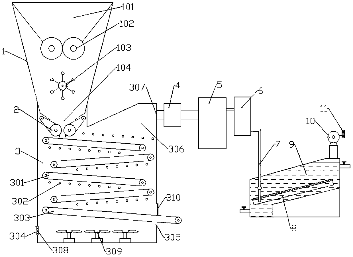
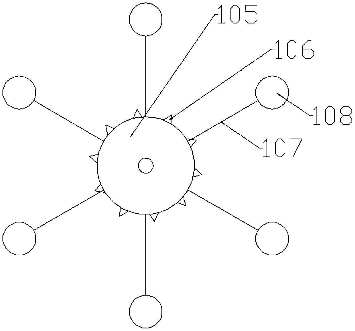
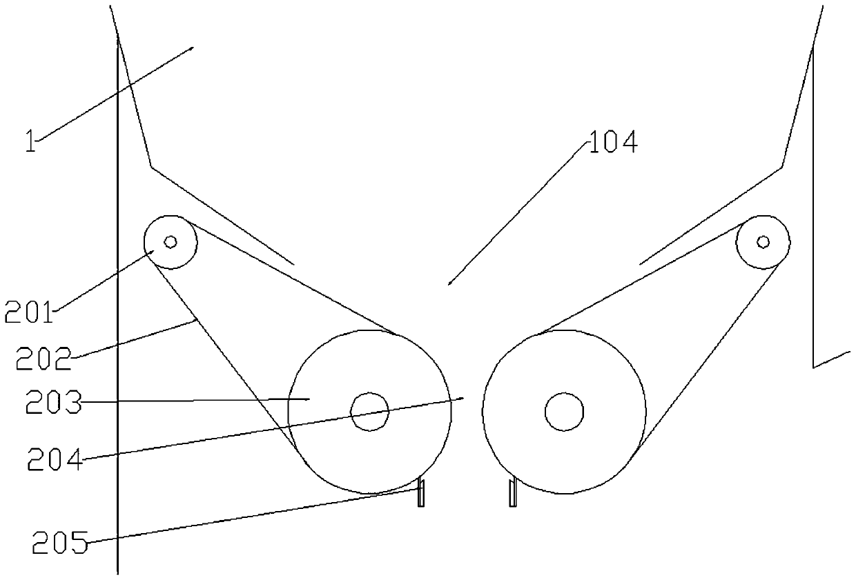
[0022] Referring to the accompanying drawings: a halocarbon-contaminated soil remediation device in this embodiment includes a halocarbon removal box 3, a hopper 1 is provided at the upper left of the halocarbon removal box 3, and a hopper 1 is provided at the top of the hopper 1. A sub-hopper 101, the bottom of the sub-hopper 101 is provided with a pulverizer 102, a soil stirring device 103 is provided below the pulverizer 102, a soil feeding port 104 is provided at the bottom of the hopper 1, and a soil rolling-off device is provided under the soil feeding port 104. Device 2, the inside of the halogenated hydrocarbon removal box 3 is provided with a number of soil conveyor belts 301 alternately "Z" from top to bottom, and the bottom of the halogenated hydrocarbon removal box 3 is provided with a soil discharge conveyor belt 303, the soil discharge conveyor belt 303 below ...


PUM


Abstract

The invention discloses a halogenated hydrocarbon-contaminated soil remediation device. The halogenated hydrocarbon-contaminated soil remediation device comprises a halogenated hydrocarbon removal box, wherein a hopper is arranged on the upper left portion of the halogenated hydrocarbon removal box, a plurality of soil conveyor belts are obliquely arranged in the halogenated hydrocarbon removal box from top to bottom alternatively in a Z-shaped mode, a soil discharging conveyor belt is arranged on the bottom of the interior of the halogenated hydrocarbon removal box, infrared ray heating modulator tubes are distributed above the soil conveyor belts and the soil discharging conveyor belt, a gas collecting cavity used for collecting hot gas flows is formed in the upper right portion of the halogenated hydrocarbon removal box, a first exhausting fan is connected with the outer portion of the gas collecting cavity, the first exhausting fan is connected with a halogenated hydrocarbon catalytic combustion furnace, the halogenated hydrocarbon catalytic combustion furnace is connected with a heat exchanger, the heat exchanger is connected with a gas inlet pipe assembly, the gas inlet pipeassembly introduces tail gas into a tail gas purification box in which an alkaline solution is placed, a gas outlet is formed in the upper right portion of the tail gas purification box, and a secondexhausting fan is arranged on the gas outlet. The halogenated hydrocarbon-contaminated soil remediation device uses infrared ray, soil heating time is long, a heated surface of soil is large, and theremediation efficiency is high.

Description

technical field [0001] The invention relates to the technical field of soil remediation, in particular to a device for remediating halogenated hydrocarbon-contaminated soil. Background technique [0002] At present, the pollution of soil organic matter has gradually become the focus of public attention, especially the pollution of halogenated hydrocarbons, which is disgusting because of its poor volatility and strong toxicity. Common products containing halogenated hydrocarbons include fire extinguishing agents (such as carbon tetrachloride), refrigerants (such as Freon), cleaning agents (common dry cleaning agents, machine parts detergents), anesthetics (such as chloroform, which are no longer used), Pesticides (such as 666, which is now banned), and raw materials for the polymer industry (such as vinyl chloride, tetrafluoroethylene), etc. Halogen is a highly toxic group, and halogenated hydrocarbons are generally more toxic than parent hydrocarbons. Many studies have sho...

Claims


Application Information

Patent Timeline
Patent Type & Authority Applications(China)
IPC IPC(8): B09C1/00B09C1/06B02C21/00B01D53/78F23G7/07
CPCB01D53/78B02C21/00B09C1/00B09C1/062F23G7/07
Inventor 谢小聪吴碎典郑挺盛
Owner 泰顺县王日飞家庭农场
Why Eureka
Try Eureka