Miniaturized antenna with reconfigurable frequency

An antenna and frequency technology, applied in the field of miniaturized antennas, can solve the problems of small gain, high processing requirements, and decreased gain.

Inactive Publication Date: 2019-07-05
BEIJING INST OF ELECTRONICS SYST ENG
View PDF3 Cites 9 Cited by
  • Summary
  • Abstract
  • Description
  • Claims
  • Application Information

AI Technical Summary

Problems solved by technology

[0007] ① Loading with lumped components, if lossy components are introduced, the efficiency will decrease and the gain will decrease;
[0008] ② Dielectric material loading will affect the bandwidth of the antenna;
[0009] ③The application of short-circuit technology loading will cause the feed structure to be sensitive to size requirements, and the processing requirements are relatively high;
The main defects of high dielectric constant dielectric substrate antennas are: large surface loss, small gain, low efficiency, and narrow bandwidth
Its characteristics are: as the length of the slot increases, the resonant frequency of the antenna decreases, and the size of the antenna decreases, but excessive reduction in size will cause a sharp degradation in performance, especially the bandwidth and gain.

Method used


Image

  • Miniaturized antenna with reconfigurable frequency
  • Miniaturized antenna with reconfigurable frequency
  • Miniaturized antenna with reconfigurable frequency

Examples


Embodiment Construction

[0055] In order to illustrate the present invention more clearly, the present invention will be further described below in conjunction with preferred embodiments and accompanying drawings. Similar parts in the figures are denoted by the same reference numerals. It should be understood by those skilled in the art that the content specifically described below is illustrative rather than restrictive, and should not limit the protection scope of the present invention with this.

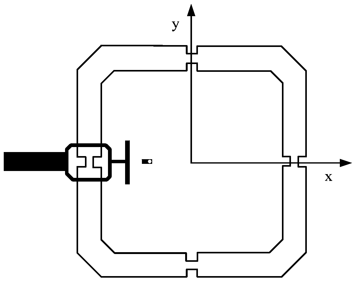
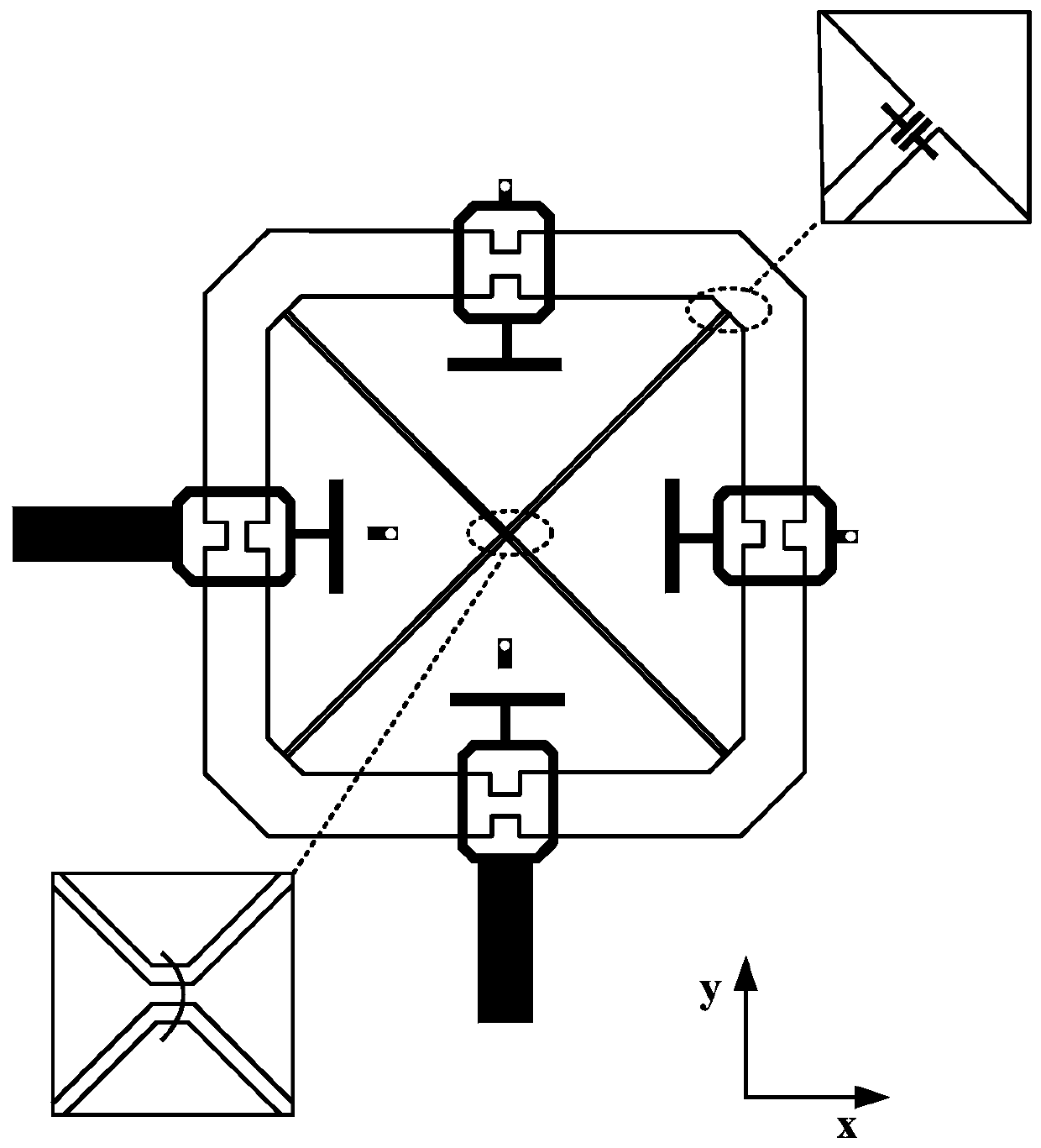
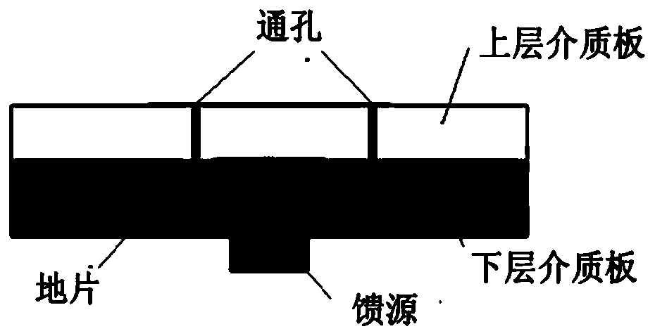
[0056] An embodiment of the present invention provides a miniaturized antenna with reconfigurable frequency, including: a ground plate; a first dielectric plate arranged on the ground plate; a coupled feeder set on the first dielectric plate; a second plate set on the coupled feeder Two dielectric plates; and a radiation unit arranged on the second dielectric plate; wherein, the ground plate is electrically connected to the radiation unit through the first through hole penetrating the first dielectric pla...


PUM


Abstract

The invention discloses a miniaturized antenna with a reconfigurable frequency, which a ground piece, a first dielectric plate arranged on the ground piece, a coupling feeder arranged on the first dielectric plate, a second dielectric plate arranged on the coupling feeder and a radiation unit arranged on the second dielectric plate, wherein the ground piece is electrically connected with the radiation unit through first through holes passing through the first dielectric plate and the second dielectric plate; and the radiation unit is of a split ring resonator structure. In the invention, the antenna size is greatly reduced through adopting the split ring resonator structure as the radiation unit and adopting a Hilbert curve to carry out splitting on SRRs (Split Ring Resonators), thereby achieving the purpose of antenna miniaturization. Meanwhile, a plurality of metal through holes are arranged on the dielectric plates to connect the radiation unit and the ground piece, and the grounding of the radiation antenna at different positions is realized by using the on-off of a variable capacitance diode so as to achieve impedance transformation, so that the number of grounded diodes is changed to adjust the number of switching frequencies.

Description

technical field [0001] The invention relates to the technical field of antennas. More specifically, it relates to a frequency reconfigurable miniaturized antenna. Background technique [0002] As a key component of the navigation equipment and the receiving end of the positioning equipment, the positioning antenna plays an important role in both transportation and daily life. With the trend of device miniaturization, antenna miniaturization has become more and more important. [0003] Antenna miniaturization refers to an antenna whose structural size is smaller compared with other types of antennas under the premise of meeting the technical indicators of the antenna, such as gain, pattern, input impedance, and polarization characteristics. We know that when the frequency is constant, the wavelength of electromagnetic waves in free space is determined. As an element that couples energy with free space, the electrical performance of the antenna is directly limited by the siz...

Claims


Application Information

Patent Timeline
Patent Type & Authority Applications(China)
IPC IPC(8): H01Q23/00H01Q5/10H01Q5/28H01Q5/307H01Q5/50H01Q7/00H01Q1/48H01Q1/50H01Q1/36
CPCH01Q1/36H01Q1/48H01Q1/50H01Q7/00H01Q23/00H01Q5/10H01Q5/28H01Q5/307H01Q5/50
Inventor 曹猛
Owner BEIJING INST OF ELECTRONICS SYST ENG
Why Eureka
Try Eureka