


Quick Research
Generate reliable direction feasibility study reports for your R&D in just a few steps.

Technical Q&A
Discover and master advanced knowledge NOW. Basics, ideas, possibilities, all at once.

Find Solutions
As an expert in R&D theories, this can generate solutions to your technical problems instantly.

Evaluate Feasibility
Analyze your overall solution with one click, know your potential R&D risks in advance.

Monitor Landscape
Get weekly tech updates, stay abreast of the latest tech innovations and key insights.
Microplastic high efficiency separation device and method
A separation device and separation method technology, applied in the direction of plastic recycling, mechanical material recycling, recycling technology, etc., can solve the problems of low separation efficiency, non-uniform size and poor separation effect of microplastics, so as to reduce manpower, material resources and time consumption, increase the frequency of collisions, and the effect of simple operations
- Summary
- Abstract
- Description
- Claims
- Application Information
AI Technical Summary
Problems solved by technology
Method used
Image


Examples
Embodiment 1
[0038] Example 1: Determination of the optimum elution flow rate for microplastics of different sizes by a high-efficiency separation device for microplastics
[0039] Sample preparation: This measurement uses plastic particles mixed with polyethylene and polypropylene with a size of 0-5mm and a certain amount of sediment, and divides the plastic particles into 0-0.2mm, 0.2-0.3mm, 0.3- The five ranges of 0.6mm, 0.6-1mm, and 1-5mm are measured separately.
[0040] Determination of the optimal flow rate: select a size range, mix a known amount of polyethylene and polypropylene mixed plastics (both of which have a density less than water) and a certain amount of sand in this range, and put them into the elution column. Use 5mol / L NaCl salt solution as the eluent, respectively 0.5L / min, 1L / min, 2L / min, 3L / min, 4L / min, 5L / min, 6L / min, 7L / min, 8L / min Min, 9L / min, 10L / min flow rate gradients for elution, calculate the recovery rate of microplastics at different flow rates, and find ...
Embodiment 2
[0049] Example 2: Comparison of elution recovery rates of different types of microplastics in eluents of different densities
[0050] Sample preparation: this determination uses a density less than 1g / cm 3 Microplastic particles mixed with polyethylene and polypropylene, density greater than 1.2g / cm 3 Polyurethane and polyvinyl chloride mixed microplastic particles and a certain amount of sediment, the size of the above four microplastic particles are all 3mm.
[0051] Determination of the recovery rate of different types of microplastics in eluents of different densities: a known quantity of polyethylene, polypropylene, polyurethane, and polyvinyl chloride mixed microplastics with a size of 3 mm was uniformly mixed with a certain amount of sediment and placed in the Into the elution column, respectively use a density of 1.2g / cm 3 NaCl salt solution and a density of 1.6 g / cm 3 The NaI salt solution was used as the eluent, and the optimal elution flow rate 9.0L / min correspon...
Embodiment 3
[0053] Example 3: Separation of microplastics in river sediments
[0054] Source and pretreatment of sediment samples: The samples used in this experiment were taken from the sediment of the upper reaches of the Qinhuai River. Take a certain amount of river bottom mud with a mud collector, pass the mud samples through mesh screens with apertures of 5mm, 1mm, 0.6mm, 0.3mm, and 0.2mm in turn, and divide the samples into 0-0.2mm, 0.2-0.3mm according to size , 0.3-0.6mm, 0.6-1mm, 1-5mm five size ranges.
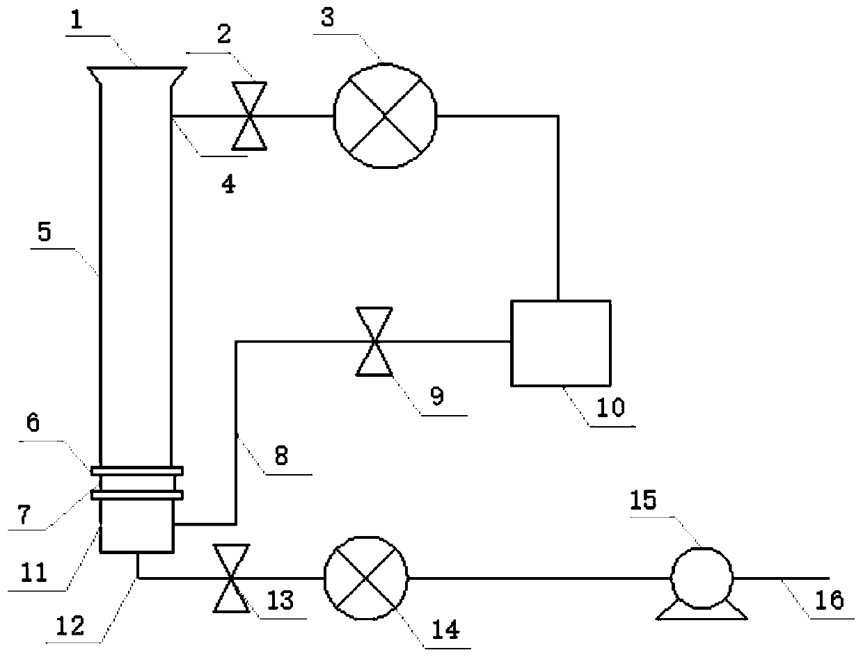
[0055] Elution and separation of microplastics: first replace the stainless steel mesh sieve 2 with a suitable pore size, and use the 37μm stainless steel mesh sieve 2 for this elution. Put the inlet into the elution column, then close the No. 2 valve 9 on the side of the shunt pipe, open the No. 3 valve 13 and the water pump 15 at the lower end of the shunt pipe, and the No. 1 valve 2 at the outlet of the microplastic, and connect the mains connected to the water pump. The wat...
PUM
| Property | Measurement | Unit |
|---|---|---|
| Aperture range | aaaaa | aaaaa |
| Aperture range | aaaaa | aaaaa |
| Size | aaaaa | aaaaa |
Abstract
Description
Claims
Application Information
 - R&D Engineer
- R&D Manager
- IP Professional
- Industry Leading Data Capabilities
- Powerful AI technology
- Patent DNA Extraction
Browse by: Latest US Patents, China's latest patents, Technical Efficacy Thesaurus, Application Domain, Technology Topic, Popular Technical Reports.
© 2024 PatSnap. All rights reserved.Legal|Privacy policy|Modern Slavery Act Transparency Statement|Sitemap|About US| Contact US: help@patsnap.com