Furnace tube installation and fixing method applied to hydrocarbon-steam conversion hydrogen production conversion furnace

A fixed method and reformer technology, applied in chemical instruments and methods, hydrogen, inorganic chemistry, etc., can solve problems such as potential safety hazards, impact on thermal efficiency, and potential safety hazards, so as to reduce excess air coefficient, reduce heat loss, and avoid welding seam cracking effect

Pending Publication Date: 2019-07-12
SHANDONG QILU PETROCHEM ENG +3
View PDF4 Cites 1 Cited by
  • Summary
  • Abstract
  • Description
  • Claims
  • Application Information

AI Technical Summary

Problems solved by technology

The lateral thrust loaded on the lower pigtail pipe can easily lead to cracking of the weld seam between it and the furnace tube and lower gas collector. Since the furnace tube, lower pigtail pipe and lower gas collector pipe contain high-temperature hydrogen, there is a potential safety hazard.
[0005] Obviously, these two fixed installation methods of the furnace tube have adverse effects on the sealing structure of the furnace tube and the furnace bottom plate.
In the former, when the hot and cold state changes, the furnace tube will be displaced laterally, causing the coaxial sealing structure to be damaged, which affects the thermal efficiency of the reformer; when the latter changes in the cold and hot state, it will affect the thermal efficiency and at the same time easily lead to the lower pigtail tube and the furnace. The weld seam of pipe and lower gas collecting pipe is cracked, posing a serious safety hazard

Method used


Image

  • Furnace tube installation and fixing method applied to hydrocarbon-steam conversion hydrogen production conversion furnace
  • Furnace tube installation and fixing method applied to hydrocarbon-steam conversion hydrogen production conversion furnace
  • Furnace tube installation and fixing method applied to hydrocarbon-steam conversion hydrogen production conversion furnace

Examples


Embodiment 1

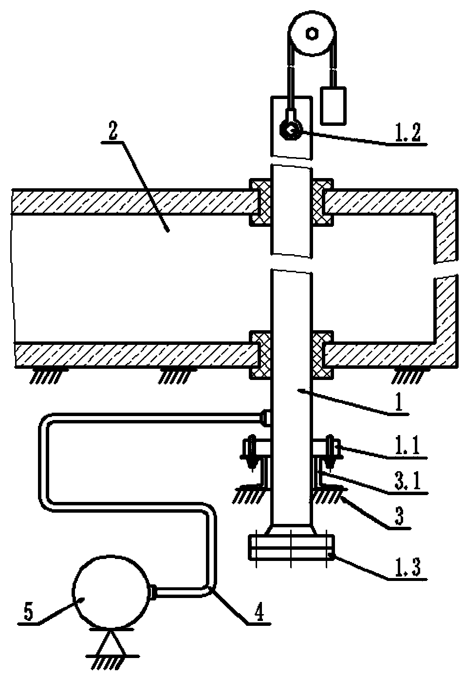
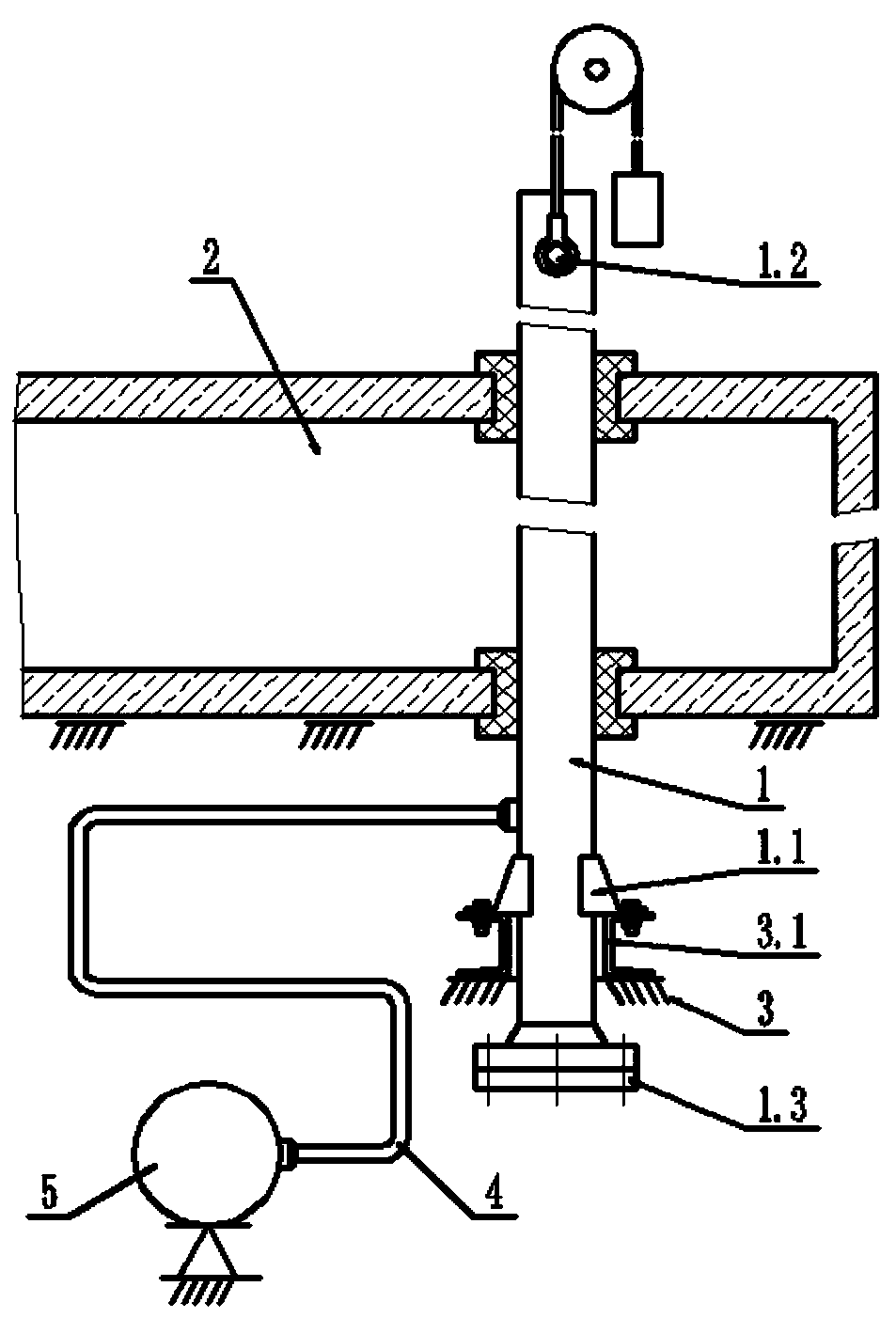
[0031] A furnace tube fixing structure applied to a hydrocarbon-steam hydrogen production reformer. The reformer includes a reformer furnace body 2 and a plurality of furnace tubes 1 arranged in multiple rows, and the plurality of furnace tubes 1 arranged in multiple rows run through vertically And stretch out the roof plate and the bottom plate of the furnace body 2 of the reformer. At the end of the furnace tube protruding downward from the furnace bottom plate, at a suitable position between the lower port flange of the furnace tube 1 and the furnace bottom plate, there are symmetrically welded fixed support members 1.1 fixedly connected with the furnace bottom steel structure. After installation, make the furnace tube 1 in a fixed state relative to the furnace bottom steel structure to avoid the sealing structure between the furnace tube 1 and the furnace bottom plate being affected by the displacement of the furnace tube 1 and the lower gas collecting pipe 4 due to thermal...

Embodiment 2

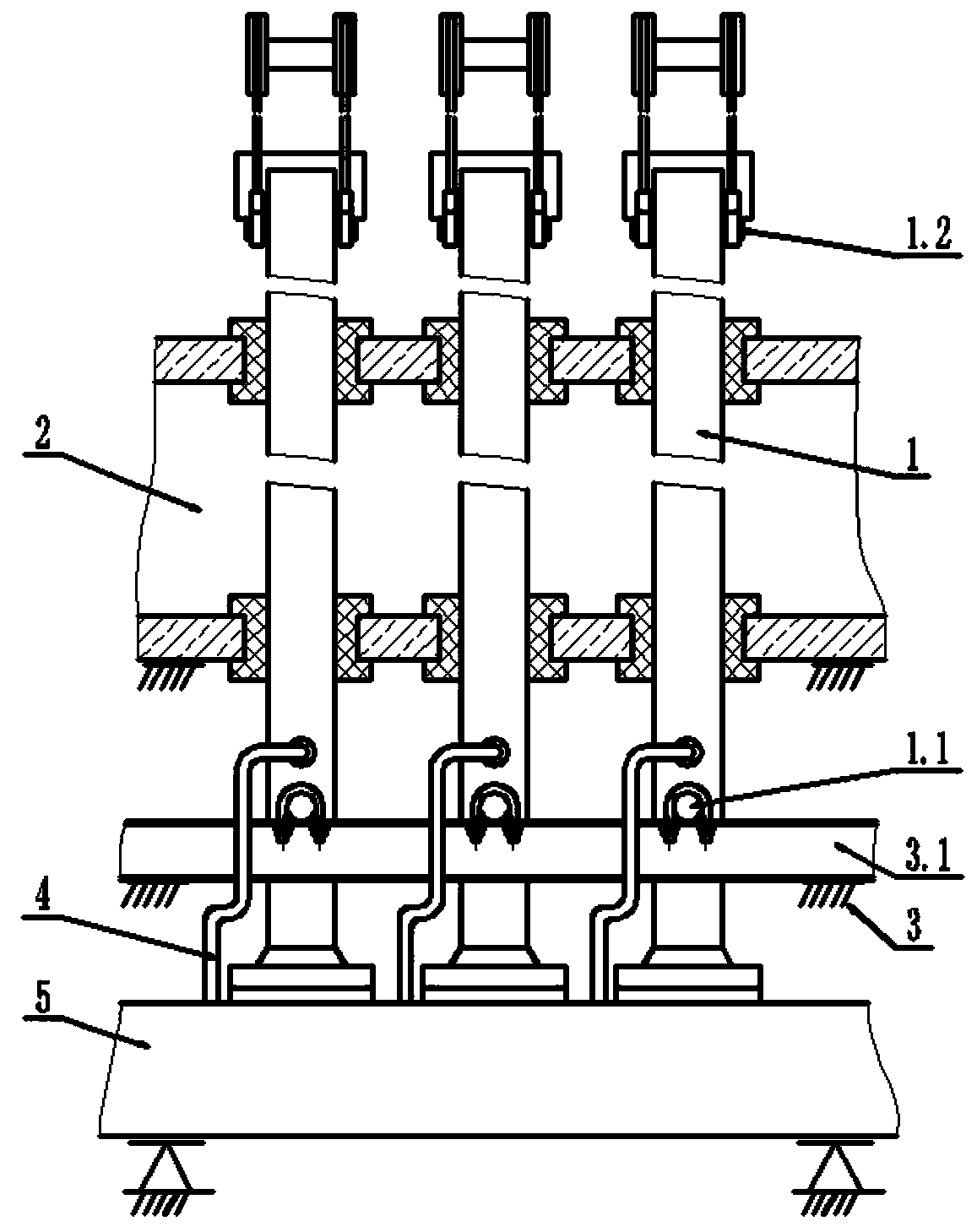
[0044] As described in Example 1, a furnace tube installation and fixing method applied to a hydrocarbon-steam reforming hydrogen production reformer, different from Example 1, such as image 3 As shown, the fixed support member 1.1 is a sheet metal part, which is symmetrically welded on both sides of the outer wall of the furnace tube 1 . The sheet metal parts on the furnace tube are placed on the channel steel 3.1, and are fixedly connected with the channel steel 3.1 by bolts.

[0045] Apparently, this connection method using sheet metal parts also achieves the effect described in Embodiment 1. There are various ways to achieve the same connection effect, which will not be repeated here.


PUM


Abstract

The invention discloses a furnace tube installation and fixing method applied to a hydrocarbon-steam conversion hydrogen production conversion furnace. The method is used for sealing connection between a plurality of rows of arranged furnace tubes and a conversion furnace body; the furnace tubes vertically penetrate through and extends out of a furnace top plate and a furnace bottom plate of the conversion furnace body; one end, stretching downwards out of the furnace bottom plate, of each furnace tube is provided with a fixing supporting piece for preventing the furnace tube from extending downwards or swinging transversely due to thermal expansion; and each fixing supporting piece is fixedly connected with a steel structure at the furnace bottom. According to the method, transverse displacement of the furnace tubes due to thermal expansion and extension of a lower gas collection tube is avoided, and coaxiality of the furnace tubes with the furnace top plate and a furnace bottom sealing structure can be guaranteed to the maximum extent, so that heat efficiency of the conversion furnace is improved, welding seam cracking caused by thermal expansion is avoided, and production safetyis ensured.

Description

technical field [0001] The invention relates to the technical field of petrochemical industry, in particular to a furnace tube installation and fixing method applied to a hydrocarbon-steam reforming hydrogen production reformer. Background technique [0002] The production of hydrogen by hydrocarbon-steam reforming is the main source of hydrogen required for hydrogenation units in the petroleum refining process, and the reformer is the core equipment of this type of hydrogen production unit. In the furnace body of the reformer, there are rows of furnace tubes running through the roof and bottom plate of the furnace. The furnace body of the reformer heats the furnace tubes, and the hydrocarbons in the furnace tubes-steam are cracked into hydrogen under the action of high temperature and catalysts in the tubes. It is sent out from the lower end of the furnace tube into the lower gas collecting pipe. [0003] At present, there are two most widely used fixed installation method...

Claims


Application Information

Patent Timeline
Patent Type & Authority Applications(China)
IPC IPC(8): C01B3/34
CPCC01B3/34Y02P20/10
Inventor 孙原田王文琦孙学波程向锋
Owner SHANDONG QILU PETROCHEM ENG
Why Eureka
Try Eureka