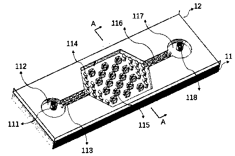
Micro-fluidic chip for capturing single cells
A microfluidic chip and single-cell technology, applied in the field of microfluidics, can solve the problem of not achieving single-cell level capture, and achieve the effect of simple structure, flexible combination, and good function realization.
- Summary
- Abstract
- Description
- Claims
- Application Information
AI Technical Summary
Problems solved by technology
Method used
Image

Examples
Embodiment 1~3
[0074] In the following examples 1-3:
[0075] 1. The preparation process of the single cell capture microfluidic chip is as follows:
[0076] (1) Silicon wafer cleaning: standard silicon wafer cleaning, placed on a 200°C electric heating plate for 15 minutes, and dried;
[0077] (2) Silicon wafer modification: place the silicon wafer in a volatilization tank, drop 1 to 2 drops of modification reagent HMDS (Hexamethyldisilazane), and volatilize for ≥ 3 minutes;
[0078] (3) Silicon wafer rejection: pour the photoresist on the processed silicon wafer, set the speed of rejection according to the required pattern depth or height, and let it stand for 1 to 2 minutes after uniform glue;
[0079] (4) Silicon wafer exposure: pre-baking process sets the pre-baking time by determining the properties of the photoresist used; the exposure process needs to consider the power of the exposure machine and the metering required for the material to set the exposure time; after exposure, deter...
Embodiment 1
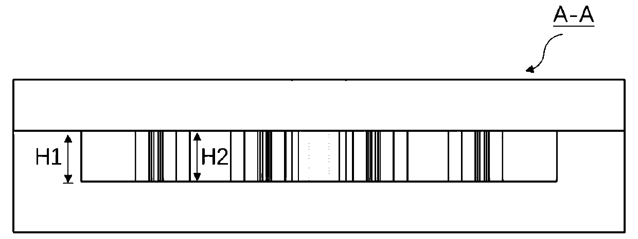
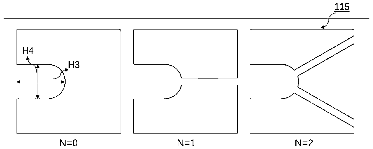
[0095] Prepare a microfluidic chip in the above way (the following microfluidic chips are referred to as chips for short), wherein the size parameters and other parameters are: H1=H2=20 μm, H3=16 μm, H4=16 μm, H5=5 μm, N=0 . The chip was washed with deionized water and phosphate buffered saline (PBS) successively with a syringe pump. Pass the cell carrier fluid into the chip, control the injection speed to 0.1 μl / s, place the chip under a microscope for observation, and finally realize the capture of single cells in the trap. Through Embodiment 1 of the present invention, the capture efficiency of single cells in the trap array reaches 96%, and the single sample consumption is effectively reduced by more than 90% compared with the same concentration of cell culture dishes.
Embodiment 2
[0097] The microfluidic chip was prepared in the above manner, wherein the size parameters and other parameters were: H1=H2=20 μm, H3=16 μm, H4=16 μm, H5=5 μm, N=1. The chip was washed with deionized water and phosphate buffered saline (PBS) successively with a syringe pump. Pass the cell carrier fluid into the chip, control the injection speed to 0.2 μl / s, place the chip under a microscope for observation, and finally realize the capture of single cells in the trap. Through Embodiment 2 of the present invention, the capture efficiency of single cells in the trap array reaches 96%, and the single sample consumption is effectively reduced by more than 95% compared with the same concentration of cell culture dishes.
PUM
 Abstract
Description
Claims
Application Information
 - R&D
- Intellectual Property
- Life Sciences
- Materials
- Tech Scout
- Unparalleled Data Quality
- Higher Quality Content
- 60% Fewer Hallucinations
Browse by: Latest US Patents, China's latest patents, Technical Efficacy Thesaurus, Application Domain, Technology Topic, Popular Technical Reports.
© 2025 PatSnap. All rights reserved.Legal|Privacy policy|Modern Slavery Act Transparency Statement|Sitemap|About US| Contact US: help@patsnap.com