Metasurface orbital angular momentum array antenna with good reflectivity

A technology of orbital angular momentum and array antennas, which is applied to antennas, antenna arrays, electrical components, etc., can solve problems such as reducing the vortex effect of electromagnetic waves, reducing antenna beam gain, and unfavorable wireless communication, so as to improve the utilization rate of unit area and improve The effect of gain and process simplification

Active Publication Date: 2019-07-12
ZHEJIANG UNIVERSITY OF SCIENCE AND TECHNOLOGY
View PDF10 Cites 7 Cited by
  • Summary
  • Abstract
  • Description
  • Claims
  • Application Information

AI Technical Summary

Problems solved by technology

This technical solution can realize the phase difference between each unit through the unit structure of the spiral structure to form a vortex electromagnetic wave, but this technical solution needs to accurately arrange the unit structure in a helical shape, which makes its production more troublesome; and the electromagnetic wave beam will It has a large diffusion effect, which leads to the reduction of antenna beam gain and the vortex effect of electromagnetic waves, which is extremely unfavorable to wireless communication

Method used


Image

  • Metasurface orbital angular momentum array antenna with good reflectivity
  • Metasurface orbital angular momentum array antenna with good reflectivity
  • Metasurface orbital angular momentum array antenna with good reflectivity

Examples


Embodiment

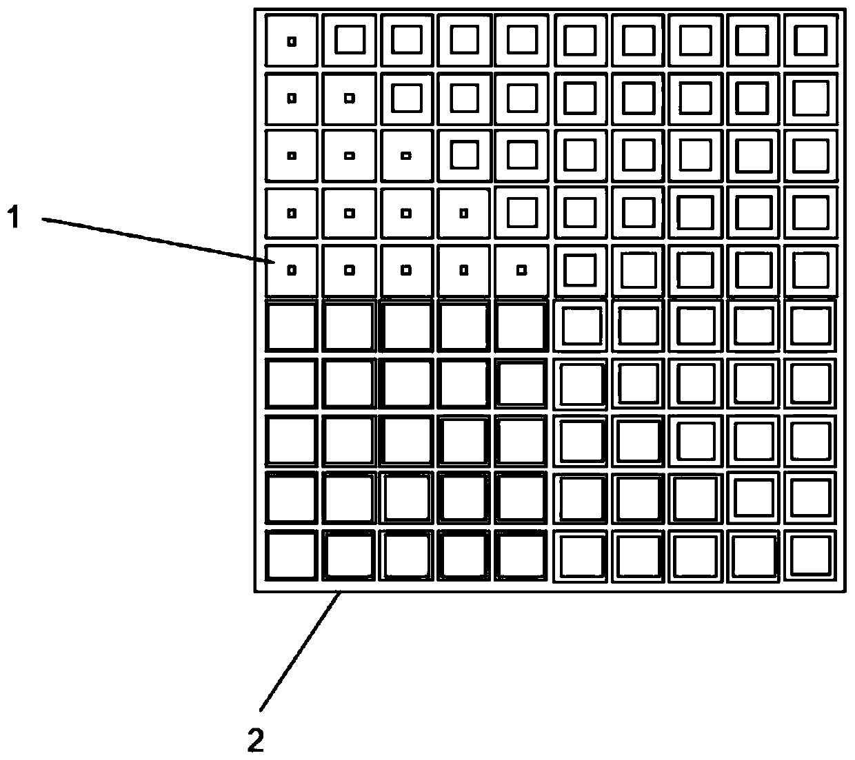
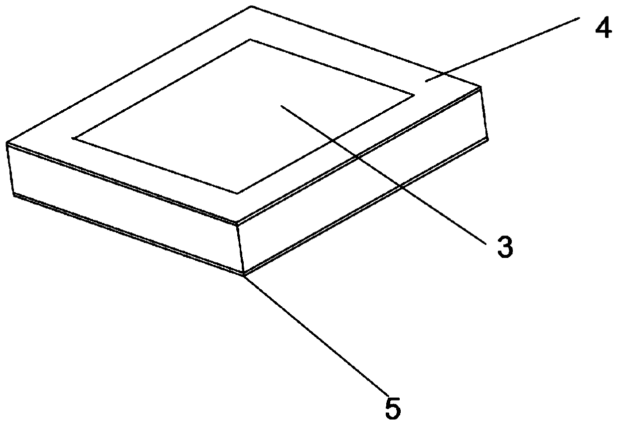
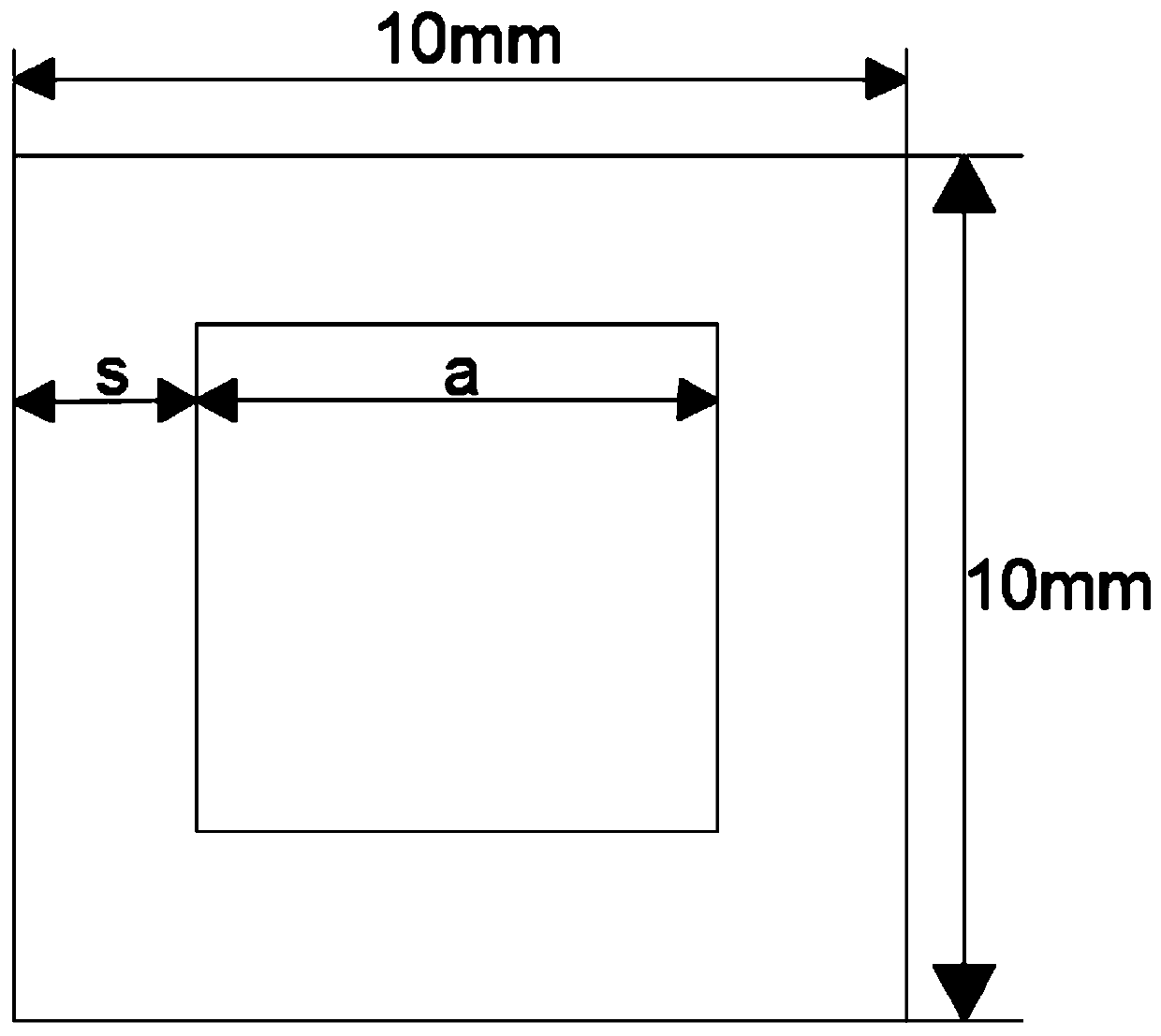
[0022] Embodiment: a metasurface orbital angular momentum array antenna with good reflectivity, as attached figure 1 As shown, the array antenna is an array phase plate 2 composed of more than two phase shifting units 1; as Figure 2-3 As shown, the phase shifting unit 1 includes a dielectric layer 3, the surface of the dielectric layer 3 is provided with a metal patch 4 in the shape of a square ring, and the width of each side of the metal patch 4 is equal; the dielectric layer 3 A metal ground layer 5 is provided at the bottom.

[0023] In order to achieve accurate control of the reflected wave front and the scattering of incident plane waves, we use array antennas to study, Figure 4 For the designed array antenna, the array antenna is square, and a total of 255 phase shifting units are spliced ​​to form an array phase plate 2. The array phase plate 1 is divided clockwise (by black thick lines) and has a first quadrant 6. The second quadrant 7, the third quadrant 8, the f...


PUM


Abstract

The invention discloses a metasurface orbital angular momentum array antenna with good reflectivity. The array antenna is an array phase plate formed by arranging more than two phase-shifting units, each phase-shifting unit comprises a dielectric layer, the surface of the dielectric layer is provided with square annular metal patches; the bottom portion of the dielectric layer is provided with metal grounding layers, the array phase plate is divided into a first quadrant, a second quadrant, a third quadrant, a fourth quadrant, a fifth quadrant, a sixth quadrant, a seventh quadrant and an eighth quadrant in the clockwise direction, the superficial area of the metal patch in each quadrant is the same, and the superficial areas of the metal patches on the phase-shifting units in the first quadrant, the second quadrant, the third quadrant, the fourth quadrant, the fifth quadrant, the sixth quadrant, the seventh quadrant and the eighth quadrant are decreased in order. The metasurface orbital angular momentum array antenna has a very excellent incident wave reflection vortex effect, the reflection efficiency can reach more than 70 percent, and the metasurface orbital angular momentum array antenna has good energy transmission efficiency; in addition, the metasurface orbital angular momentum array antenna has the advantages of the simple structure, high utilization rate of unit areasof the phase-shifting units, the simple manufacturing process and the low cost.

Description

technical field [0001] The invention relates to a metasurface orbital angular momentum array antenna with good reflectivity, which belongs to the communication field. Background technique [0002] The angular momentum of electromagnetic waves includes spin angular momentum and orbital angular momentum. As an important physical quantity in physics, orbital angular momentum (OAM) has rapidly promoted the new development of nonlinear optics, quantum optics, atomic optics and astronomy since it was confirmed by Allen et al. in 1992. Different from the spin angular momentum, the orbital angular momentum is associated with the helical phase wave front, which can theoretically take infinite values ​​and be orthogonal to each other. Electromagnetic waves carrying orbital angular momentum are different from ordinary plane waves. The center intensity of the beam is zero, and the phase wave front presents a spiral characteristic, also known as vortex electromagnetic waves. The vortex...

Claims


Application Information

Patent Timeline
Patent Type & Authority Applications(China)
IPC IPC(8): H01Q15/00H01Q3/34H01Q3/46H01Q21/00
CPCH01Q15/0086H01Q3/34H01Q3/46H01Q21/00
Inventor 徐弼军童鑫闫梦瑶孙志超
Owner ZHEJIANG UNIVERSITY OF SCIENCE AND TECHNOLOGY
Why Eureka
Try Eureka