Multi-material gradient forming fusion extrusion system for 3D printing

A melt extrusion, multi-material technology, applied in the field of material processing, can solve the problems of inability to achieve real-time adjustment and control of the proportion of heterogeneous multi-material components, inability to overcome the problems of FDM wire breakage, blocking nozzles, and inability to achieve composition gradient forming, etc. Achieving the effect of easy control, reduced possibility, and convenient operation

Pending Publication Date: 2019-07-16
HUAZHONG UNIV OF SCI & TECH
View PDF4 Cites 9 Cited by
  • Summary
  • Abstract
  • Description
  • Claims
  • Application Information

AI Technical Summary

Problems solved by technology

At present, the mainstream pellet feed processing feed system is mainly for single material extrusion processing, such as invention patents CN108466423A, CN108327252A, etc., which melt and extrude the pellets in the form of a screw, which can realize the layer-by-layer accumulation of pellets. However, in the process of processing, it is impossible to achieve real-time adjustment and control of the composition ratio of heterogeneous multi-materials, that is, it is impossible to realize composition gradient forming; the invention patent CN107263858B realizes the manufacture of heterogeneous materials in the form of traditional wire FDM, which uses rotary multi-nozzle switching The printing device performs multi-material and multi-process high-efficiency 3D printing by rotating and switching multiple wire feeding and printing mechanisms. However, the possibility of gradient processing and forming is not mentioned, and the traditional wire form cannot overcome the broken wires of FDM itself. The problem of nozzle blockage; utility model patent CN208035395U discloses a high-viscosity gradient material 3D printer feeding system, which mainly pumps high-viscosity materials into the screw valve processing chamber through an air pump, PU tube, etc., and can adjust the printing nozzle to output high-viscosity printing in real time The type of material, but for granular materials, which cannot be pumped by air pumps, etc.
[0005] Therefore, for inorganic nonmetals and their composite materials, the research on heterogeneous multi-material gradient forming is less, and it is in a blank state. It is urgent to develop a multi-material gradient forming melt extrusion system for 3D printing to solve the above problems.

Method used


Image

  • Multi-material gradient forming fusion extrusion system for 3D printing
  • Multi-material gradient forming fusion extrusion system for 3D printing
  • Multi-material gradient forming fusion extrusion system for 3D printing

Examples


Embodiment 1

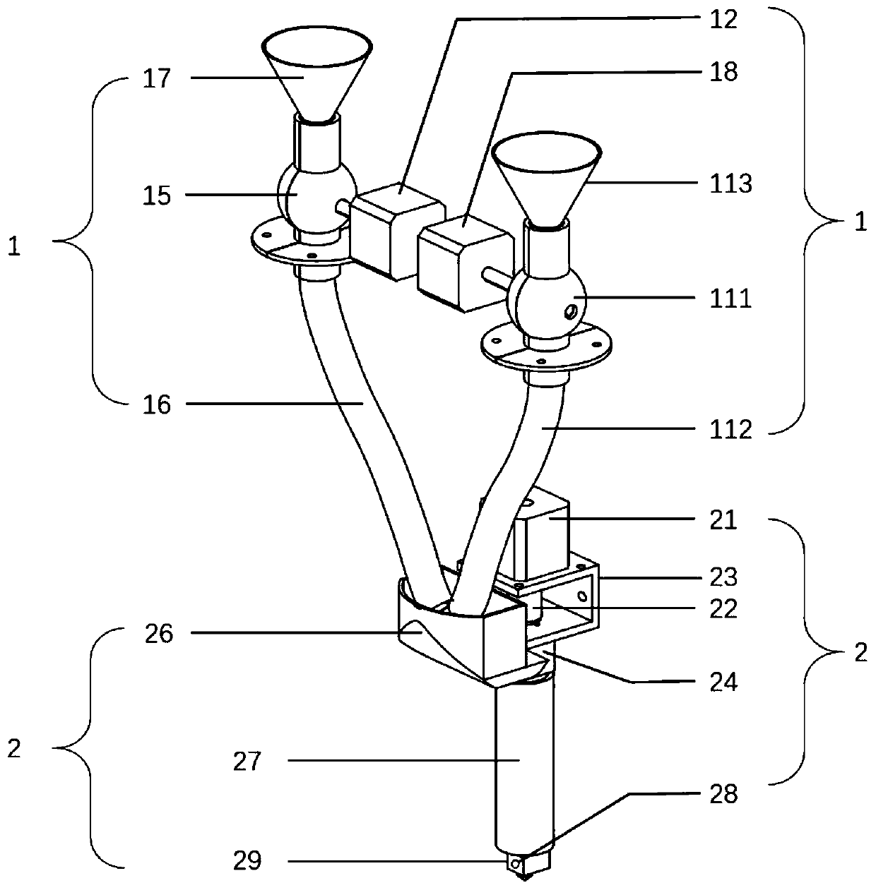
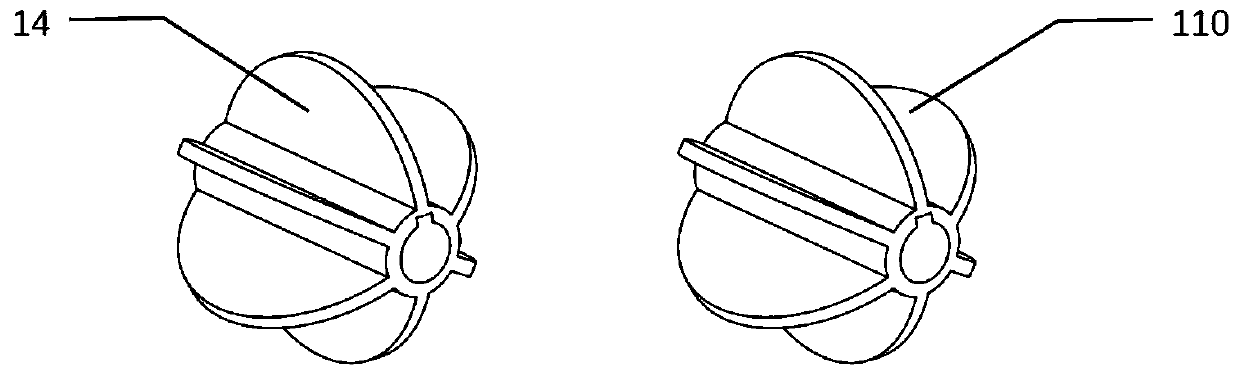
[0046] The first embodiment provided by the present invention is as figure 1 As shown, it includes two parts: a particle differential transmission mechanism 1 and a particle melting extrusion mechanism 2 , and the particle differential transmission mechanism 1 is fixed above the particle melting extrusion mechanism 2 . The particle differential transmission mechanism 1 comprises a first discharge motor 12, a first discharge rotary blade 14, a first stagnation cylinder 15, a first particle conduit 16 and a first charging funnel 17; a second discharge motor 18, a second Discharge rotary blade 110, the second stagnant cylinder 111, the second particle conduit 112 and the second charging funnel 113; the first discharge rotary blade 14 is arranged in the first stagnant cylinder 15, and the first discharge The rotary handle of the material rotating blade 14 is connected with the rotating shaft of the first discharge motor 12 through the small hole on the side of the first material s...

Embodiment 2

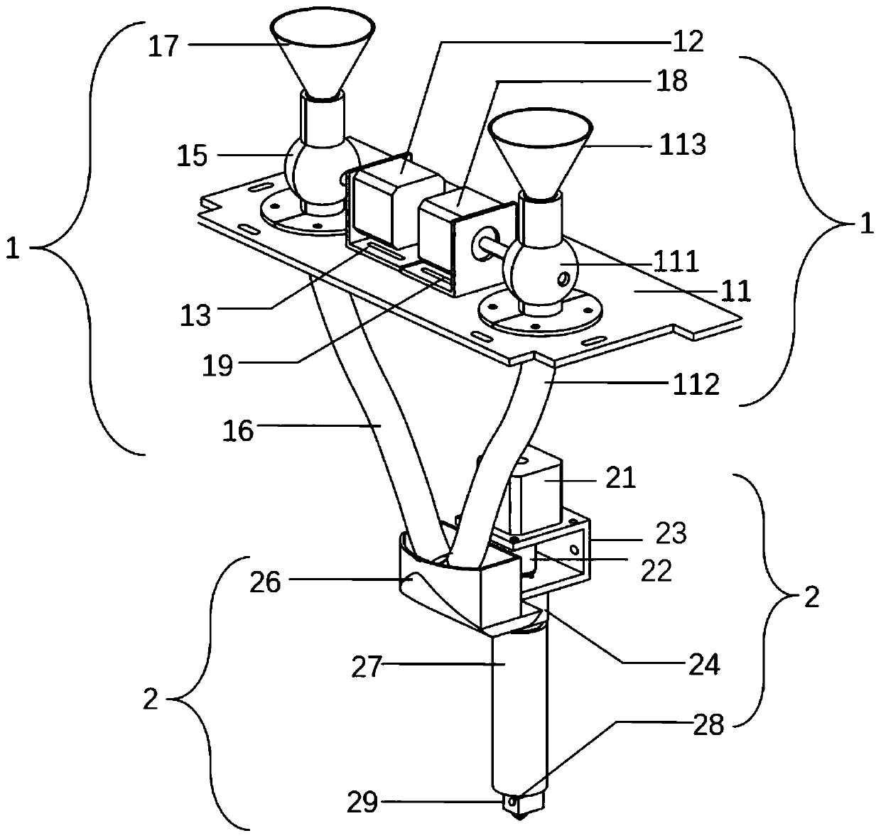
[0052] like figure 2 In this embodiment, on the basis of Embodiment 1, a support substrate 11, a first discharge motor support 13 and a second discharge motor support 19 are also provided in the particle differential transmission mechanism 1, and the first stagnation cylinder 15 and the second stagnant barrel 111 are respectively fixed on the support substrate 11 through flanges, and the corresponding parts of the support substrate 11 and the first stagnant barrel 15 and the second stagnant barrel 111 are provided with two circular through holes , the lower ends of the first sluggish cylinder 15 and the second sluggish cylinder 111 respectively pass through the respective circular through holes, and are connected with the upper ends of the first particle conduit 16 and the second particle conduit 112; the first discharge motor 12 The first discharging motor bracket 13 is fixed on the supporting substrate 11 ; the second discharging motor 18 is fixed on the supporting substrat...

Embodiment 3

[0055] In this embodiment, on the basis of Embodiment 2, the parameters of each component are as follows:

[0056] The first discharge motor 12 and the second discharge motor 18 are 42 series two-phase stepping motor standard parts;

[0057] The first stagnation cylinder 15 and the second stagnation cylinder 111 are customized parts for processing, and the diameter of the top cylinder is Height 35mm, middle sphere diameter Lower cylinder diameter Height 10mm, wall thickness 3mm;

[0058] The first charging funnel 17 and the second charging funnel 113 are standard parts, top diameter lower diameter 70mm high;

[0059] The first discharge motor support 13 and the second discharge motor support 19 are 42 series two-phase stepper motor fixed support standard parts;

[0060] The support substrate 11 is a custom-made part made of transparent acrylic, the length*width*thickness is 390mm*156mm*5mm respectively, and the diameters of the holes punched on it are The length a...


PUM

PropertyMeasurementUnit
thicknessaaaaaaaaaa

Abstract

The invention belongs to the field of material machining, and discloses a multi-material gradient forming fusion extrusion system for 3D printing. The multi-material gradient forming fusion extrusionsystem for 3D printing comprises two parts of a particle differential transmission mechanism and a particle fusion extrusion mechanism. According to the multi-material gradient forming fusion extrusion system for 3D printing, the gradient forming of heterogeneous multi-materials is realized by controlling the feeding amount of different kinds of particles in the forming process; and by adopting the system, the wire material machining can be changed into particle processing, and the 3D printing of composite polymer materials can be supported by mixing two kinds of polymer particles together. The composition control of two kinds of polymer mixed particles is realized, and the composition proportion of printing materials is enabled to be controllable so as to realize 3D printing of the functionally gradient heterogeneous multi-materials; and the range of usable materials is expanded by flexible machining,the production cost is reduced, and the occurrence of the problems of wire breaking,blockage of a spray headand the like in wire machining is avoided.

Description

technical field [0001] The invention belongs to the field of material processing, and relates to a multi-material gradient forming melt extrusion system for 3D printing. Background technique [0002] Fused Deposition Modeling (FDM) is a kind of 3D printing technology, which was successfully developed by American scholar Scott Crump in 1988. The materials used in this technology are generally thermoplastic materials, such as polylactic acid PLA, ABS, wax, etc., and are supplied in the form of filaments with a fixed diameter, and the materials are heated and melted in the nozzle. The nozzle moves along the section profile of the part and the filling track, and at the same time extrudes the molten material. The material solidifies rapidly and condenses with the surrounding materials, and the formed part is obtained by layer-by-layer accumulation. However, once the silk material is drawn into silk, its composition and content are fixed, and it cannot be customized according to ...

Claims


Application Information

Patent Timeline
Patent Type & Authority Applications(China)
IPC IPC(8): B29C64/118B29C64/20B29C64/336B33Y30/00B33Y40/00
CPCB29C64/118B29C64/20B29C64/336B33Y30/00B33Y40/00
Inventor 魏青松李继康张弛钟狄珈赵生玉黄涛石婷杨柳青马晓杰史玉升
Owner HUAZHONG UNIV OF SCI & TECH
Why Eureka
Try Eureka