Fischer-Tropsch slag wax treatment device and treatment process

A treatment device and treatment process technology, which is applied in the treatment of hydrocarbon oil, petroleum industry, petroleum wax refining, etc., can solve the problems of low recovery rate of heavy wax and solvent, complicated operation process, etc., and achieve high degree of equipment centralization and process flow Simple and effective in reducing environmental pollution

Active Publication Date: 2021-03-16
CHNA ENERGY INVESTMENT CORP LTD +1
View PDF3 Cites 0 Cited by
  • Summary
  • Abstract
  • Description
  • Claims
  • Application Information

AI Technical Summary

Problems solved by technology

[0007] The purpose of the present invention is in order to overcome the problems such as complicated operation process, heavy wax and solvent recovery rate that existing slag wax processing technology exists, thereby provide a kind of new treatment device and processing technology of Fischer-Tropsch slag wax

Method used


Image

  • Fischer-Tropsch slag wax treatment device and treatment process

Examples


Embodiment 1

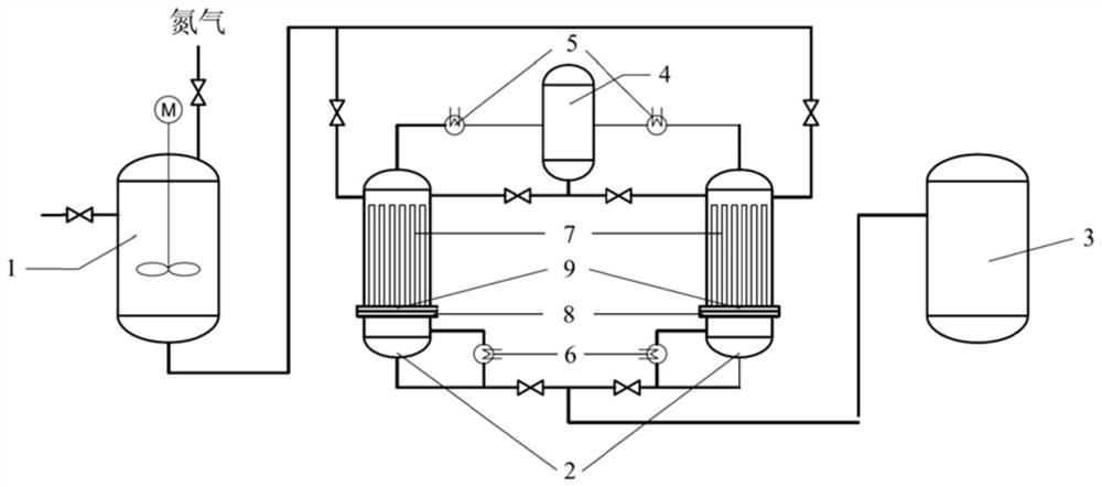
[0072] The slag wax (heavy wax content is 70% by weight) in the slag wax storage tank 1 is stirred, and the temperature of maintaining the slag wax is at 110-130 ℃, guarantees that the slag wax is in a flowing state, then feeds nitrogen, and the slag wax Press into the slag wax filtration extraction tank 2, maintain the filtration pressure difference at 0.1-0.3MPa by controlling the nitrogen to carry out the filtration operation, after filtration, pump the obtained heavy wax into the recovery heavy wax storage tank 3, and remove the remaining The slag wax (ie the first slag wax residue, wherein the heavy wax content is 50% by weight) is extracted. Toluene (consumption is 3 times of the volume of the first slag wax residue) is sent into the reboiler 6 for gasification at 150° C., and the toluene gas obtained enters the condenser 5 after passing through the tubular filter 7 (the temperature is 10-15 ℃) to condense, then enter the slag wax filtration extraction tank 2 after the e...

Embodiment 2

[0074] Stir the slag wax (heavy wax content 70% by weight) in the slag wax storage tank 1, and maintain the temperature of the slag wax at 130-150°C to ensure that the slag wax is in a flowing state, then feed nitrogen to press the slag wax into the slag wax filtration extraction tank 2, and maintain the filtration pressure difference at 0.3-0.5MPa by controlling nitrogen to carry out the filtration operation. After filtration, the heavy wax obtained is pumped into the recovery heavy wax storage tank 3, and the remaining The slag wax (ie the first slag wax residue, heavy wax content is 40% by weight) is extracted. Toluene (consumption is 6 times of the volume of the first slag wax residue) is sent into the reboiler 6 for gasification at 130° C., and the obtained toluene gas enters the condenser 5 (the temperature is 12-15 ℃) condenses, then enters the slag wax filtration extraction tank 2 to extract the first slag wax residue after passing through the extraction solvent recove...


PUM

PropertyMeasurementUnit
particle sizeaaaaaaaaaa

Abstract

The invention relates to the field of coal indirect liquefaction, and discloses a treatment device and treatment process for Fischer-Tropsch synthesis residue wax. The process comprises the followingsteps: 1) performing filtration on the residue wax to obtain first residue wax residues and heavy wax, and recovering the heavy wax; 2) performing extraction on the first residue wax residues by usingan extraction solvent to obtain second residue wax residues and a second liquid-phase material flow containing the extraction solvent and the heavy wax; and 3) performing separation on the second liquid-phase material flow to obtain the heavy wax and the extraction solvent, and recovering the heavy wax and the extraction solvent, respectively. The treatment process for the residue wax provided bythe invention adopts a method that firstly filtration separation is performed and secondly solvent extraction separation is performed to recover the heavy wax in the residue wax, thereby greatly improving a recovery rate of the heavy wax and the extraction solvent, and improving the economic benefits; and the process flow is simple.

Description

technical field [0001] The invention relates to the field of indirect coal liquefaction, in particular to a Fischer-Tropsch slag wax treatment device and treatment process. Background technique [0002] Fischer-Tropsch synthesis refers to the reaction in which synthesis gas is converted to hydrocarbons on a catalyst. Through Fischer-Tropsch synthesis, the synthesis gas converted from coal, natural gas and biomass can be converted into liquid fuel under the action of a catalyst, which is an important way for clean coal conversion. . The slurry bed Fischer-Tropsch synthesis process has gradually become the mainstream process of Fischer-Tropsch synthesis due to its advantages of good heat extraction and high production capacity. [0003] In the slurry bed Fischer-Tropsch synthesis, in order to ensure the continuous operation of the device, it is necessary to periodically remove the deactivated catalyst in the reactor in the form of slurry, and at the same time to separate the ...

Claims


Application Information

Patent Timeline
Patent Type & Authority Patents(China)
IPC IPC(8): C10G73/42
CPCC10G73/42C10G2300/1022
Inventor 张奉波门卓武孟祥堃胡云剑王涛卜亿峰
Owner CHNA ENERGY INVESTMENT CORP LTD
Why Eureka
Try Eureka