
Preparation method of insulated isolation coating suitable for high-temperature piezoelectric sensor

A technology of insulation isolation and high-temperature piezoelectricity, which is applied in the direction of coating, metal material coating process, ion implantation plating, etc., can solve the problems of expensive equipment, high cost of film growth, and poor process compatibility, so as to improve stability and Accuracy, Achieve Part Integrity, High Film Cohesion Results

Inactive Publication Date: 2019-07-16
SOUTHWESTERN INST OF PHYSICS +1
View PDF5 Cites 1 Cited by
  • Summary
  • Abstract
  • Description
  • Claims
  • Application Information

AI Technical Summary

Problems solved by technology

However, the growth temperature of MOCVD and MBE films is relatively high, generally around 1000°C, the process compatibility is poor, and the equipment is very expensive, resulting in the disadvantages of high film growth cost and low yield.
Micron-submicron-sized particles are likely to exist in the film prepared by PLD, and the area of ​​the prepared film is limited, which cannot meet the requirements of large-area and mass production

Method used


Image

  • Preparation method of insulated isolation coating suitable for high-temperature piezoelectric sensor
  • Preparation method of insulated isolation coating suitable for high-temperature piezoelectric sensor
  • Preparation method of insulated isolation coating suitable for high-temperature piezoelectric sensor

Examples


Embodiment 1

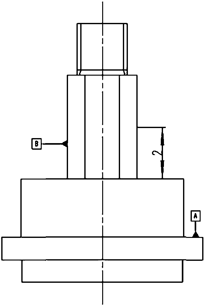
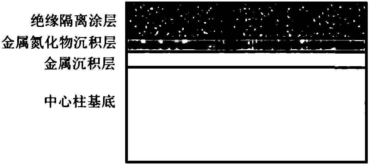
[0045] figure 1 It is the first embodiment of the present invention - a schematic diagram of the structure of the metal deposition layer / insulating isolation coating, which is the central support part of the piezoelectric sensor, and the manufacturing method includes the following steps:

[0046] Step 1. Pretreatment of central column

[0047] 1.1 gasoline ultrasonic cleaning for 15 minutes;

[0048] 1.2 Rinse with deionized water;

[0049] 1.3 Alcohol ultrasonic cleaning for 15 minutes;

[0050] 1.4 Ultrasonic cleaning with deionized water for 10 minutes;

[0051] 1.5 Dry with compressed air;

[0052] 1.6 Vacuum drying at 150°C for 120 minutes;

[0053] Step 2. Center column installation

[0054] The central column is assembled in the fixture of the deposition coating, and the part of the deposition coating is exposed, and the other parts are strictly protected by the cover of the tooling to prevent the deposition of the coating; then the central column and the tooling ...

Embodiment 2

[0071] Embodiment 2: The difference between this embodiment and the specific embodiment 1 is that in step 5, the type of the transition layer is adjusted to be Al. Others are the same as in Example 1.

Embodiment 3

[0072] Embodiment 3: The difference between this embodiment and the specific embodiment 1 is that in step 5, the type of the transition layer is adjusted to be Cr. Others are the same as in Example 1.


PUM

PropertyMeasurementUnit
thicknessaaaaaaaaaa

Abstract

The invention belongs to the technical field of electron device preparation, and particularly relates to a preparation method of an insulated isolation coating suitable for a high-temperature piezoelectric sensor. The preparation method of insulated isolation coating suitable for the high-temperature piezoelectric sensor comprises the steps of installing and fixing after pretreating a center column, then placing into a vacuum chamber, heating, baking, degassing, sputter cleaning, and then carrying out transition layer deposition and insulated isolation coating deposition. Micron-order ceramicmetallic oxide or metallic oxide is deposited on a center support structure so as to be used as the insulated isolation coating, so that the insulated isolation of positive and negative lead structures is realized; and the coating has a stable insulation performance and a high film layer binding force, can solve the problems such as linear expansion and decomposition of a traditional insulated sleeve pipe under severe environment conditions such as high temperature and high impact, and realizes component integrity, so that the stability and the accuracy of electron devices are improved, and the product quality is stable.

Description

technical field [0001] The invention belongs to the technical field of electronic device preparation, and in particular relates to a preparation method of a high-temperature alloy steel-based insulating and isolating coating. Background technique [0002] The central support structure (central column) of the piezoelectric sensor is assembled inside the sensor and is in an airtight shell structure. During assembly, its surface will be in contact with the positive and negative lead structures of the piezoelectric sheet, so its surface insulation must be ensured, and a voltage of 100V is required. The test should not be lower than 100 megohms. If the surface insulation is not good, it will cause a short circuit between the positive and negative poles of the sensor, and the sensor will fail and lose its function. High-temperature piezoelectric shock sensors are used in harsh environments such as high temperature and high impact. The insulation reliability of the central support ...

Claims


Application Information

Patent Timeline
Patent Type & Authority Applications(China)
IPC IPC(8): C23C14/32C23C14/02C23C14/06
CPCC23C14/0021C23C14/022C23C14/025C23C14/0641C23C14/325
Inventor 但敏金凡亚颜复秀陈美艳赵云华许泽金
Owner SOUTHWESTERN INST OF PHYSICS
Learn More