Biomolecule detection chips and detection system based on optical flow control

A technology of biomolecules and detection chips, which is applied to the measurement of phase influence characteristics, etc., can solve the problems of increasing equipment costs and testing costs, and achieve the effects of less sample demand, avoiding negative effects, and low manufacturing costs

Active Publication Date: 2019-07-16
LIANGZHUN SHANGHAI MEDICAL EQUIP CO LTD
View PDF7 Cites 2 Cited by
  • Summary
  • Abstract
  • Description
  • Claims
  • Application Information

AI Technical Summary

Problems solved by technology

Although the sensitivity of SPR can reach the nanometer level, the sensor not only needs to use polarized light with a fixed wavelength as the light source, but also needs to coat a very thin metal film (about 50 nanometers) on the prism, which will increase the equipment cost and test cost.
In addition, the traditional SPR sensing detection process requires the use of laboratory centrifuges to centrifuge whole blood samples and other pretreatment processes to obtain serum before detection can be performed

Method used


Image

  • Biomolecule detection chips and detection system based on optical flow control
  • Biomolecule detection chips and detection system based on optical flow control
  • Biomolecule detection chips and detection system based on optical flow control

Examples


Embodiment 1

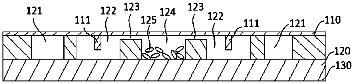
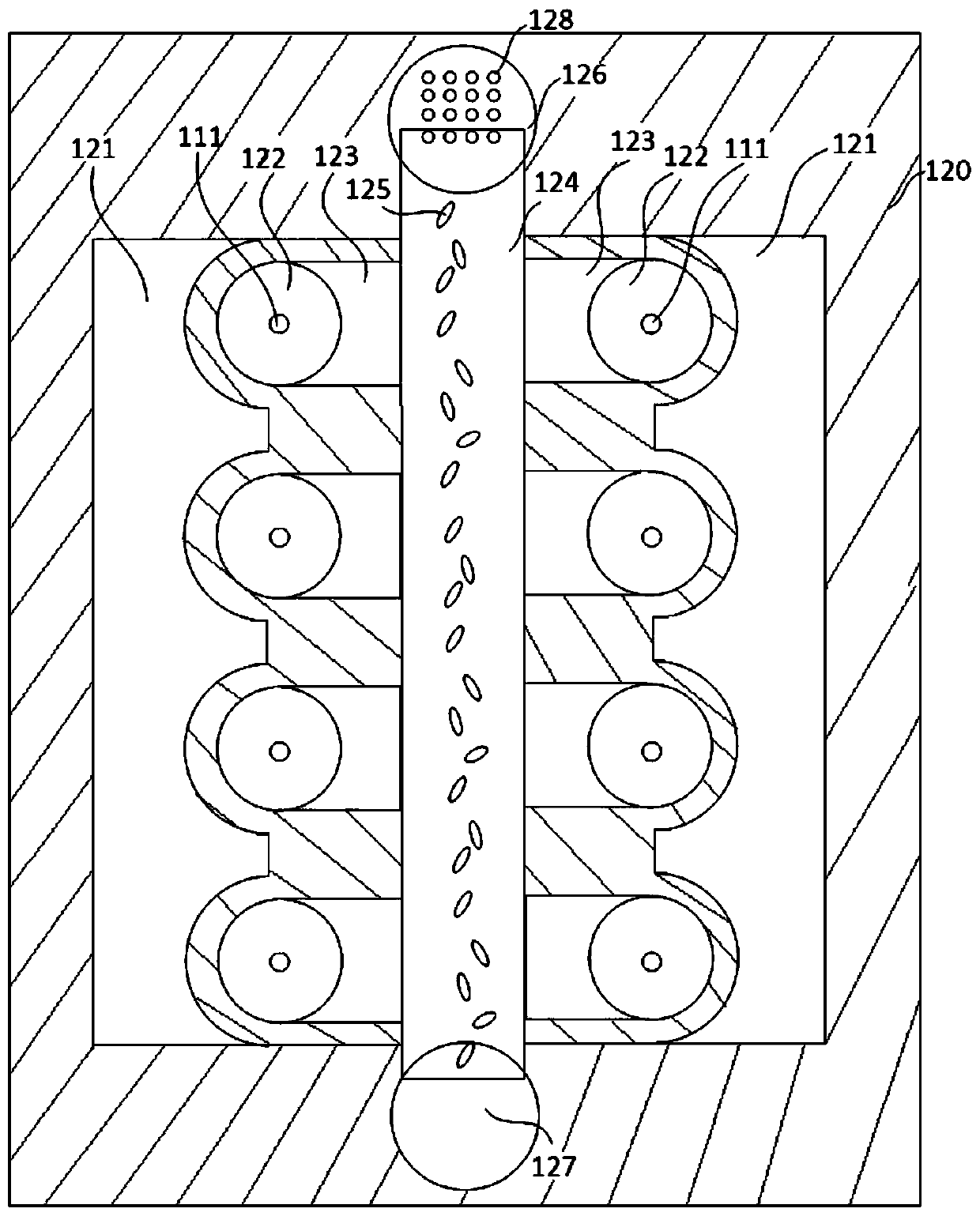
[0034] Such as figure 1 and figure 2As shown, the present invention has a sandwich structure consisting of an upper layer 110 , a middle layer 120 and a lower layer 130 to form a body. The upper layer 110 is a transparent hard polymer material, such as polystyrene (PS), acrylic (PMMA), etc., which is processed by injection molding or other methods. The cylindrical waveguide 111 is used for molecular detection of the analyte. The waveguide 111 and the upper layer 110 are processed by one-time injection molding, and the outer surface and end of the waveguide 111 have standard specular reflection characteristics through polishing. In order to reduce the scattering of the incident light in the upper layer 110 when the incident light enters the waveguide 111 or the reflected light is reflected from the waveguide 111 , the thickness of the upper layer 110 is controlled at 50-100 microns. The lower layer 130 is a flexible polymer material, such as acrylonitrile-butadiene-styrene c...

Embodiment 2

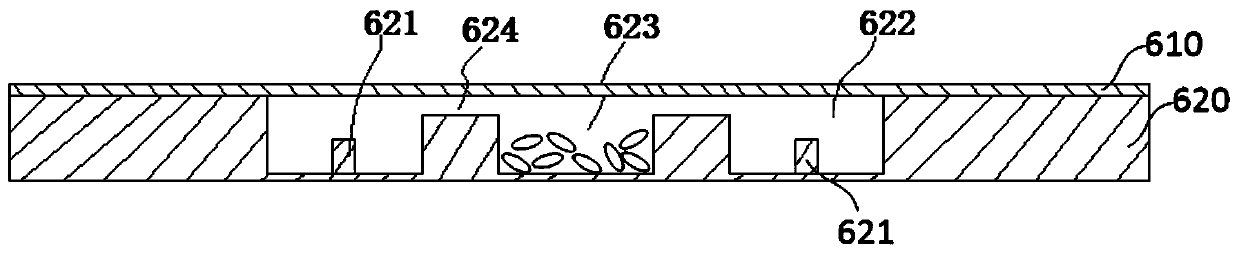
[0036] Such as image 3 As shown, the present invention consists of an upper layer 610 and a lower layer 620 forming a body. The lower layer 620 is provided with a main microchannel 623 and a detection chamber 622 , and the main microchannel 623 and the detection chamber 622 are communicated through a microslit 624 . In this embodiment, the main microchannel 623 communicates with the detection chamber 622 with an interface (not shown in the figure) provided on the body, and the interface is used to connect the pumping equipment, so that the detection chamber 622 and the main microchannel 623 negative pressure inside. The upper layer 610 is a flexible polymeric sealing film. The lower layer 620 is a microfluidic functional structure made of hard polymer, which is processed by injection molding or other methods. The cylindrical waveguide 621 is used for molecular detection of the analyte, and the waveguide 621 and the lower layer 620 are processed by one injection molding and...

Embodiment 3

[0038] Such as Figure 4 and Figure 5 As shown, the present invention is provided with at least one filter area 722 between the main microflow channel and the detection cavity, and there is a micro-slit 713 between the filter area 722 and the upper surface of the body; at least one waveguide 711 is arranged in the detection cavity 723, and the waveguide 711 is located On the inner side of the upper surface of the main body; an output port 721 is provided at the end of the detection chamber 723, and an absorbent pad 730 is provided under the main body. Specifically, the present invention consists of an upper layer 710 and a lower layer 720 to form a body. The upper layer 710 is a microfluidic functional structure made of hard polymer, which is processed by injection molding or other methods. The cylindrical waveguide 711 is used for molecular detection of the analyte, and the waveguide 711 and the upper layer 710 are processed by one injection molding and the outer surface a...


PUM

PropertyMeasurementUnit
thicknessaaaaaaaaaa
thicknessaaaaaaaaaa
thicknessaaaaaaaaaa

Abstract

The invention discloses biomolecule detection chips based on optical flow control. A biomolecule detection chip comprises a body, wherein a master micro-channel and a detection cavity are set in the body. The master micro-channel and the detection cavity are communicated through utilization of a micro-gap. The micro-gap is located at an upper part in the body. A sample input port is set on the body. The sample input port is communicated with the master micro-channel. A waveguide stretching into the detection cavity is set on an upper surface or a lower surface in the body. The waveguide is a cylinder of which outer surface and tail end have a standard mirror reflection characteristic. A surface on which the waveguide is set is a transparent surface. The biomolecule detection chip also comprises a mechanism which enables negative pressure to be formed in the detection cavity and the master micro-channel, or an interface which enables the detection cavity and the master micro-channel tobe connected with air extraction equipment. The condition that preprocessing processes such as centrifugation are carried out on a whole blood sample to obtain serum and then detection can be carriedout is avoided. Whole blood is added to the master micro-channel from the sample input port, blood cells of the whole blood in the micro-channel are deposited, the serum flows into the detection cavity through utilization of the micro-gap under an effect of the negative pressure and capillary force, and the serum can be detected.

Description

technical field [0001] The invention relates to biomolecular detection technology, in particular to a biomolecular detection chip and detection system based on optofluidic control. Background technique [0002] Affinity biosensors play an important role in the fields of medicine, pharmacy, agriculture and scientific research. This type of sensor utilizes the interaction between the receptor and the analyte to realize the detection and analysis of the existence and concentration of the analyte and the binding force between the receptor and the analyte. Common receptor-analyte combinations include complementary nucleic acid chains, antibodies and antigens, proteins and ligands, nucleic acids and ligands, etc. [0003] Affinity biosensors usually first modify the receptor on the solid sensing interface, and place the solid sensing interface in the sample containing the analyte molecules, and the interaction between the receptor and the analyte on the solid sensing interface oc...

Claims


Application Information

Patent Timeline
Patent Type & Authority Applications(China)
IPC IPC(8): G01N21/45
CPCG01N21/45
Inventor 刘文朋刘钢胡友德孙英豪许锦龙曹笈
Owner LIANGZHUN SHANGHAI MEDICAL EQUIP CO LTD
Why Eureka
Try Eureka