
Filter for carbon ion terahertz characteristic spectral line detection and preparation method thereof

A characteristic spectral line and terahertz technology, which is applied in the field of terahertz and semiconductor micromachining, can solve the problems that affect the transmittance, cannot meet the fine structure characteristic spectral line detection of carbon ions, reduce the transmittance, etc., and achieve simple composition, Improved reliability, integrability, and ease of operation

Inactive Publication Date: 2019-07-16
SHANGHAI NORMAL UNIVERSITY
View PDF6 Cites 1 Cited by
  • Summary
  • Abstract
  • Description
  • Claims
  • Application Information

AI Technical Summary

Problems solved by technology

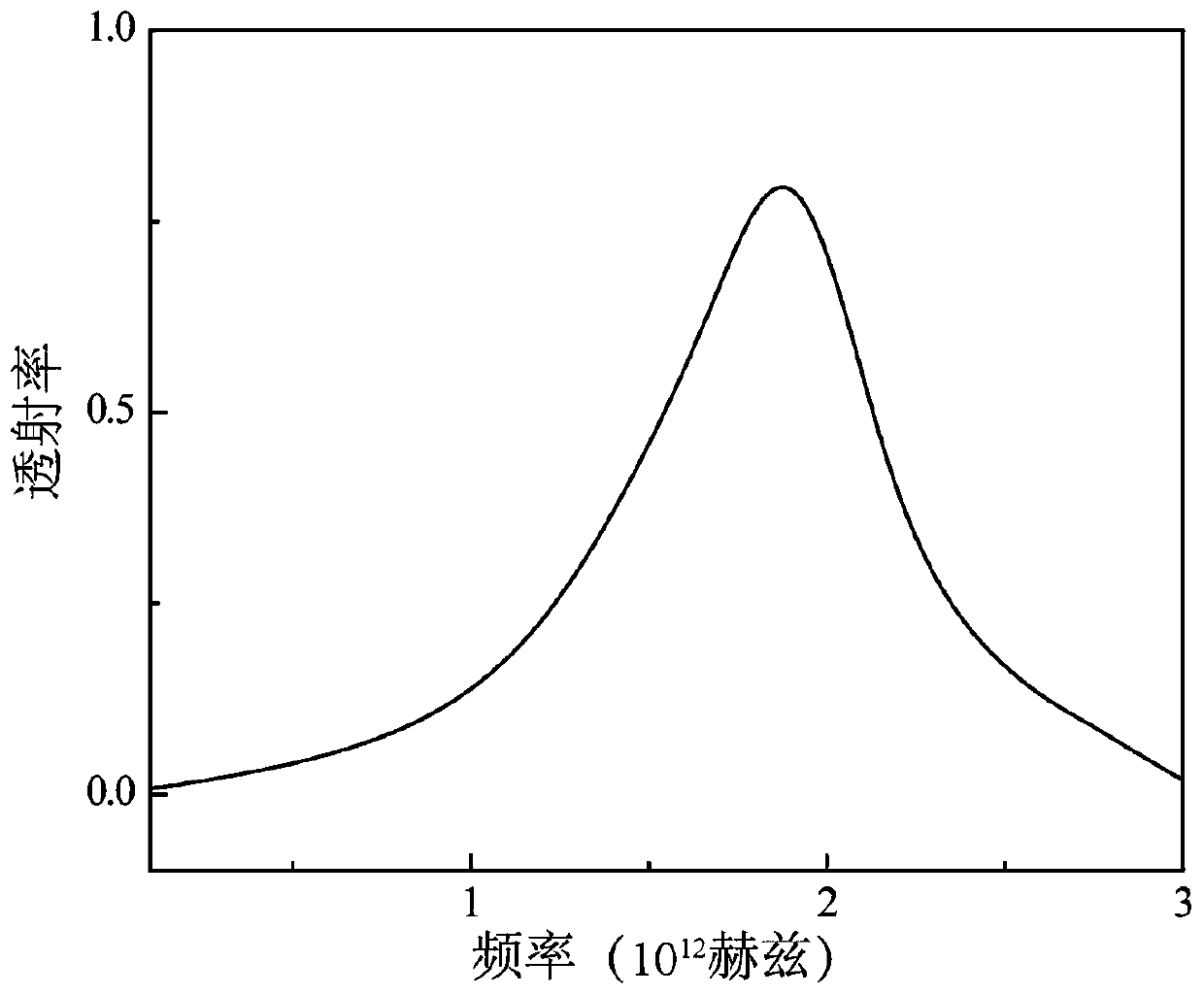
[0004] The published patent "Filter Resonant Unit and Manufacturing Method for Nitrogen Ion Terahertz Characteristic Line Detection (Patent No.: ZL201510035761.5)" uses the Babinet principle to design a filter resonant unit similar to a Christian cross structure. The center frequency of the overrate channel is located at 1.45THz, which cannot satisfy the detection of the fine structure characteristic lines of carbon ions
If only the cross structure is changed, although the center frequency can be shifted, the corresponding transmittance will be reduced. In particular, the patent uses gallium arsenide semiconductor as the substrate, and there is unavoidable free carrier absorption, which affects the transmittance.

Method used


Image

  • Filter for carbon ion terahertz characteristic spectral line detection and preparation method thereof
  • Filter for carbon ion terahertz characteristic spectral line detection and preparation method thereof
  • Filter for carbon ion terahertz characteristic spectral line detection and preparation method thereof

Examples


Embodiment Construction

[0016] Below in conjunction with accompanying drawing and embodiment the present invention is further described

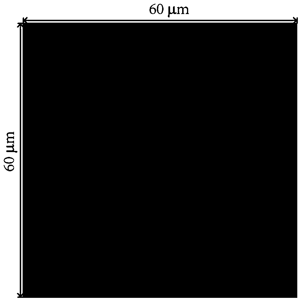
[0017] Filters for the detection of carbon ion terahertz characteristic lines (as attached figure 1 shown). It includes the main horizontal axis 1, the secondary horizontal axis 2, and the vertical axis 3, wherein the vertical axis 3 passes through the middle of the main horizontal axis 1 and the secondary horizontal axis 2.

[0018] The resonance unit is a metal hollow layer, the substrate is a polyimide with a thickness of 25 μm, and the metal layer of the resonance unit is a 200nm gold layer.

[0019] Further, the main horizontal axis 1 is 16 μm long and 3 μm wide;

[0020] The secondary horizontal axis 2 is 8 μm long and 2 μm wide;

[0021] The longitudinal axis 3 is 49 μm long and 2 μm wide;

[0022] The distance from the lower edge of the main horizontal axis 1 to the center of the vertical axis 3 is 9 μm;

[0023] The lower edge of the secondary horizon...


PUM


Abstract

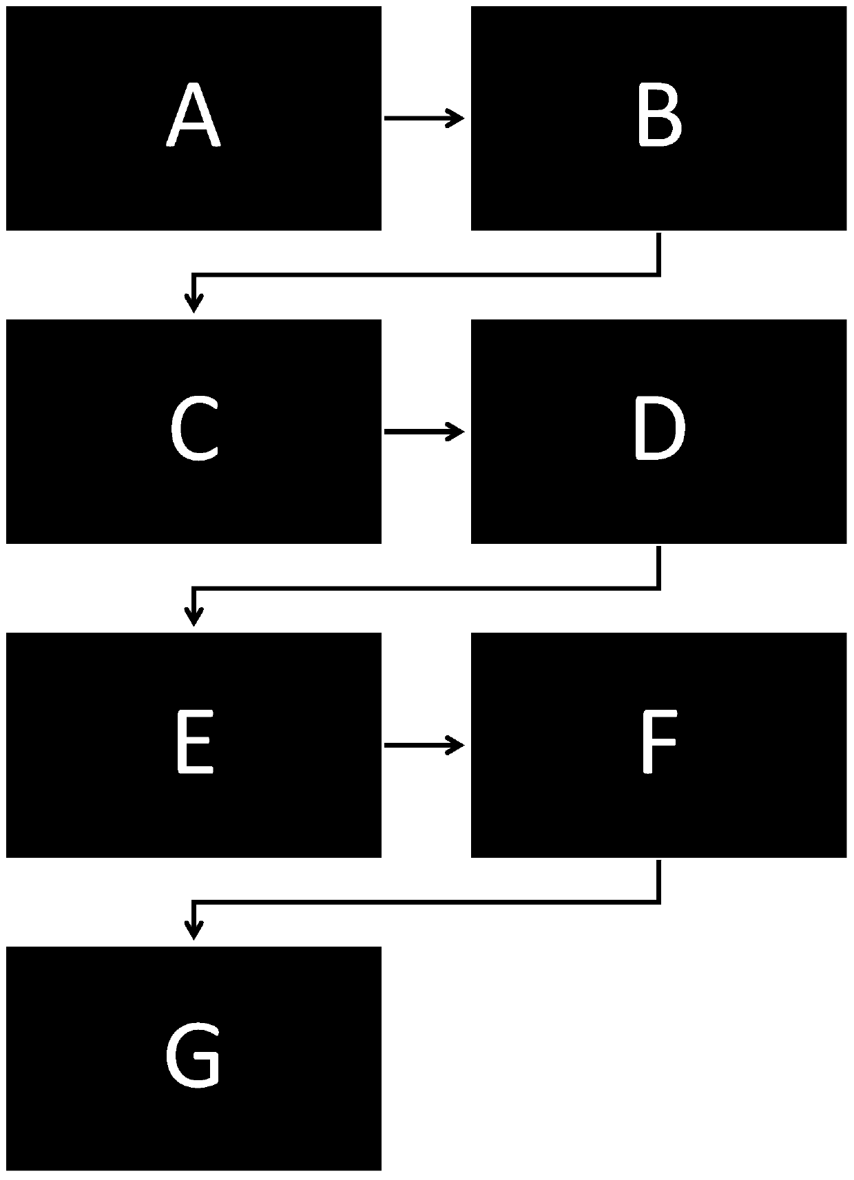
The invention discloses a filter for carbon ion terahertz characteristic spectral line detection and a preparation method thereof, and relates to the technical field of terahertz and semiconductor micro-processing. The filter for carbon ion terahertz characteristic spectral line detection comprises a main transverse shaft, a secondary transverse shaft, and a longitudinal shaft, wherein the longitudinal shat penetrates through the middle of the main transverse shaft and the secondary transverse shaft. A resonance unit is a metal hollow-out layer; a substrate is polyimide with the thickness of 25 microns; and the metal layer of the resonance unit is a 200 nm gold layer. The preparation method comprises the following steps of step A, putting the polyimide substrate subjected to laser processing into deionized water; carrying out other steps; and step G, clamping a product by using ceramic tweezers, slowly shaking in an acetone solution, and stripping the extra metal layer after the photoresist is corroded by acetone, and forming a hollowed-out Orthodox-type cross type resonance unit which is consistent with the design pattern on one side of the periodic microstructure. The method hasthe advantages of simple process, convenient operation and low cost. High adhesion can be obtained without annealing, so that the reliability and the integration of the device are improved.

Description

technical field [0001] The invention relates to the technical field of terahertz and semiconductor micromachining, and specifically refers to a terahertz (THz) system based on a semi-insulating gallium arsenide (SI-GaAs) polyimide (Polyimide) surface with a hollow Orthodox cross-shaped resonant unit. Design and fabrication of bandpass filters. Background technique [0002] Reflecting the physical behavior of the cold neutron gas in the Milky Way in astrophysics requires tracing the fine-structure characteristic line of carbon ions: 158 μm / 1.9 terahertz (THz). In order to obtain high-definition THz astronomical images, it is necessary to have a high-sensitivity THz astronomical detection device. At present, the superconducting edge transition sensor (TES) that uses the principle of thermal impedance changes caused by superconducting phase transitions to detect cosmic THz radiation and the microwave energy inductance detector (MKID) that uses microwaves to excite Cooper elect...

Claims


Application Information

Patent Timeline
IPC IPC(8): H01P1/20H01P7/08H01P11/00
CPCH01P1/20H01P7/08H01P11/007H01P11/008
Inventor 赵振宇顾志东
Owner SHANGHAI NORMAL UNIVERSITY
Learn More