Broadband tunable high-precision optical fractional Fourier converter and implementation method thereof
A fractional Fourier, high-precision technology, applied in optical fiber transmission, electromagnetic wave transmission systems, electrical components, etc., can solve the problem of low speed and bandwidth, low resolution, large storage space and Computational costs, etc.
- Summary
- Abstract
- Description
- Claims
- Application Information
AI Technical Summary
Problems solved by technology
Method used
Image
Examples
Embodiment 1
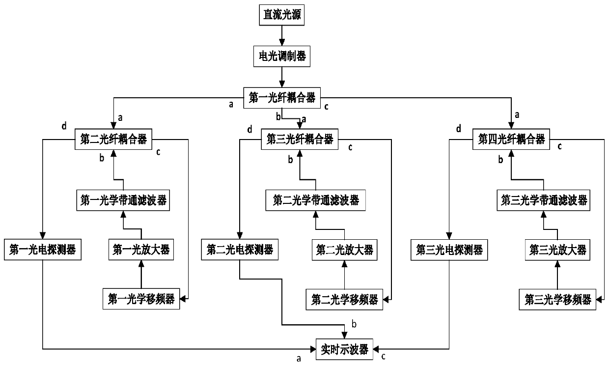
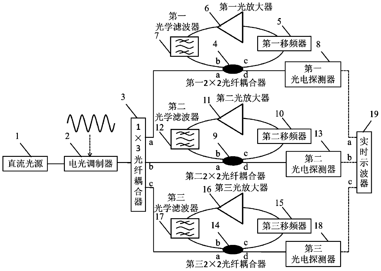
[0035] Such as figure 2 As shown, a broadband tunable high-precision optical fractional Fourier transformer includes a DC light source 1, an electro-optical modulator 2, a 1×3 fiber coupler 3, a first 2×2 fiber coupler 4, a first shift Frequency optical loop, first photodetector 8, second 2×2 optical fiber coupler 9, second frequency shift optical loop, second photodetector 13, third 2×2 optical fiber coupler 14, third frequency shift optical ring Road, the third photodetector 18, real-time oscilloscope 19. The DC light source 1 generates a DC optical carrier, and the microwave signal to be processed is modulated on the envelope of the optical carrier by the electro-optic modulator 2; the electro-optic modulator 2 is biased at a linear bias point, and its output is connected to the 1 The input of ×3 fiber coupler 3; the a port of the 1×3 fiber coupler 3 is connected to the a port of the first 2×2 fiber coupler 4, for inputting the first channel modulation signal into the fir...
Embodiment 2
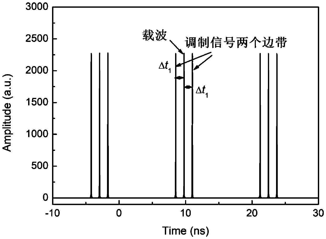
[0037] Such as figure 2 As shown, the DC light source 1 outputs a DC optical carrier, and the linearly biased electro-optic intensity modulator 2 modulates the microwave signal on the envelope of the DC optical carrier. The modulated signal is divided into three channels with equal power through a 1×3 fiber coupler. The modulated signals of the three channels are respectively input from the a input ports of the three 2×2 fiber couplers 4, 9, and 14, and then simultaneously from the c port and d port output. The c-port output signals of the three 2×2 optical fiber couplers 4, 9, and 14 are respectively used as the input signals of the first, second, and third frequency-shifting optical rings, and are sequentially passed through the three optical fiber frequency shifters 5, 10, and 15 respectively. Realize the frequency shift amount is f s1 , f s2 , f s3 The frequency shift copy of the three optical amplifiers 6, 11, 16 is used to compensate the power loss in the three loop...
PUM
 Abstract
Description
Claims
Application Information
 - R&D
- Intellectual Property
- Life Sciences
- Materials
- Tech Scout
- Unparalleled Data Quality
- Higher Quality Content
- 60% Fewer Hallucinations
Browse by: Latest US Patents, China's latest patents, Technical Efficacy Thesaurus, Application Domain, Technology Topic, Popular Technical Reports.
© 2025 PatSnap. All rights reserved.Legal|Privacy policy|Modern Slavery Act Transparency Statement|Sitemap|About US| Contact US: help@patsnap.com


