
Preparation method of alloy wire for wireless charging and multi-target magnetron sputtering device for preparation

A magnetron sputtering device and magnetron sputtering technology, applied in the direction of metal extrusion control equipment, sputtering coating, metal processing equipment, etc., can solve the problem of low output power, low coil permeability, slow charging speed, etc. problems, to achieve the effect of improving magnetic coupling efficiency, excellent performance, and convenient production

Active Publication Date: 2019-07-23
ZHEJIANG TONY ELECTRONICS CO LTD
View PDF5 Cites 1 Cited by
  • Summary
  • Abstract
  • Description
  • Claims
  • Application Information

AI Technical Summary

Problems solved by technology

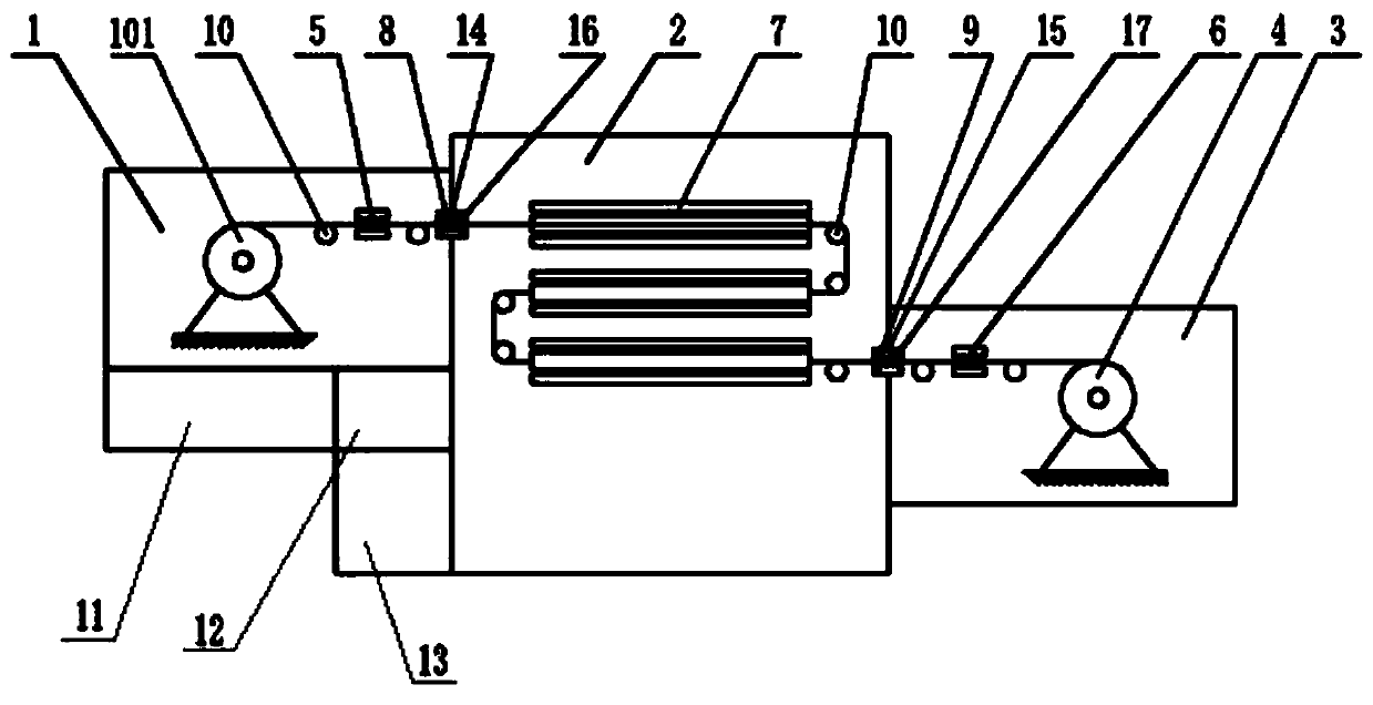
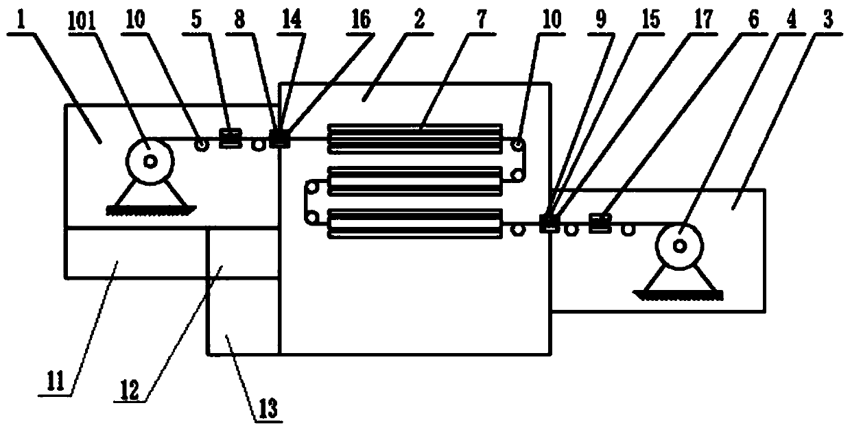
[0005] The purpose of the present invention is to provide a method for preparing an alloy wire for wireless charging and a multi-target magnetron sputtering device for the preparation, so as to at least solve the problems of low output power and slow charging speed caused by the low magnetic permeability of the current wireless charging equipment coil

Method used


Image

  • Preparation method of alloy wire for wireless charging and multi-target magnetron sputtering device for preparation
  • Preparation method of alloy wire for wireless charging and multi-target magnetron sputtering device for preparation

Examples


Embodiment Construction

[0043] The present invention will be described in detail below with reference to the accompanying drawings and examples. It should be noted that, in the case of no conflict, the embodiments in the present application and the features in the embodiments can be combined with each other.

[0044] In the description of the present invention, the terms "longitudinal", "transverse", "upper", "lower", "front", "rear", "left", "right", "vertical", "horizontal", " The orientations or positional relationships indicated by "top", "bottom", etc. are based on the orientations or positional relationships shown in the drawings, and are only for the convenience of describing the present invention and do not require that the present invention must be constructed and operated in a specific orientation, so they cannot be understood as Limitations on the Invention. The terms "connected" and "connected" used in the present invention should be understood in a broad sense, for example, it can be fi...


PUM

PropertyMeasurementUnit
lengthaaaaaaaaaa
lengthaaaaaaaaaa

Abstract

The invention belongs to the field of alloy wire preparation, and particularly discloses a preparation method of an alloy wire for wireless charging and a multi-target magnetron sputtering device forpreparation. The alloy wire is formed by iron and copper, the mass percent of the iron ranges from 20 wt% to 40 wt%, and the copper coats the outer surface of a copper wire. The pure iron layer on theouter portion of the alloy wire has good magnetic permeability, the magnetic coupling efficiency of a receiving coil can be improved, and therefore the wireless charging power and efficiency are improved. The preparation method of the alloy wire comprises the steps that firstly, the copper wire of the proper size is selected; then, alloy wire base metal is prepared and obtained through the multi-target magnetron sputtering device; the surface of the copper wire is plated with iron in a multi-target magnetron sputtering manner, and the thickness of pure iron on the surface of the wire is guaranteed; and finally, drawing is carried out, the alloy wire base metal is drawn, and a finished product of the alloy wire for wireless charging is prepared. According to the preparation method of the alloy wire, preparation is convenient, pollution is low, the pure iron plating layer of the alloy wire is uniform, and great significance is achieved in development of the wire for wireless charging.

Description

technical field [0001] The invention belongs to the field of alloy wire preparation, and in particular relates to a method for preparing an alloy wire for wireless charging and a multi-target magnetron sputtering device for the preparation. Background technique [0002] With the development of wireless charging technology, more and more electronic products have realized the wireless charging function. At present, wireless charging is mostly realized by electromagnetic induction coupling. The principle of electromagnetic induction coupling is that the magnetic fields generated by the transmitting coil and the receiving coil interact The coupling between them realizes wireless charging, but the current wireless charging power is small and the charging time is long, which cannot meet the high-power and high-efficiency wireless charging requirements of electronic products. [0003] In the existing electromagnetic induction coupling wireless charging equipment, the coils at the t...

Claims


Application Information

Patent Timeline
Patent Type & Authority Applications(China)
IPC IPC(8): C23C14/35C23C14/16C23C14/54C22C9/00H01B13/00B21C1/00B21C3/02B21C31/00
CPCB21C1/003B21C3/02B21C31/00C22C9/00C23C14/165C23C14/3464C23C14/35C23C14/545H01B13/0006H01B13/0026
Inventor 曹军
Owner ZHEJIANG TONY ELECTRONICS CO LTD
Learn More