A method for cleaning and purifying sulfur-containing tail gas

A tail gas cleaning and tail gas technology, applied in chemical instruments and methods, separation methods, gas treatment, etc., can solve the problems of rapid diffusion of unfavorable tail gas, low desulfurization efficiency of activated carbon, unstable process operation, etc., to reduce adverse effects and small pore size , the effect of more active sites

Active Publication Date: 2021-07-02
安徽皖华环保设备科技有限公司
View PDF6 Cites 0 Cited by
  • Summary
  • Abstract
  • Description
  • Claims
  • Application Information

AI Technical Summary

Problems solved by technology

However, the efficiency of activated carbon desulfurization is low, and it is easily affected by the previous treatment process. The micropores are blocked by impurities in the tail gas and affect the activity, and the process operation is unstable. In addition, the tail gas temperature after activated carbon desulfurization is generally low, which is not conducive to tail gas Rapid diffusion, easy to form smog

Method used


Image

  • A method for cleaning and purifying sulfur-containing tail gas

Examples

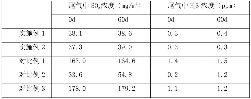

Embodiment 1

[0025] A method for cleaning and purifying sulfur-containing tail gas, comprising the following steps:

[0026] (1) The acidic sulfur-containing tail gas is passed into the combustion furnace for treatment at 1100 ° C. The treated gas is first passed into the waste heat boiler for waste heat recovery, and then passed into the first-level Claus reactor, the first-level Claus reactor The inlet temperature is 235°C. After the reaction is carried out in the first-stage Claus reactor, it is cooled to 150°C by the first-stage condenser, and then heated to 225°C by the heat exchanger, and then passed into the second-stage Claus reactor. After the reaction, it is cooled to 150°C by the secondary condenser to condense and separate the liquid sulfur to be collected through the liquid sulfur trap, and the Claus tail gas after the liquid sulfur is separated enters the next step of treatment;

[0027] (2) Send the Claus tail gas to the bottom of the spray tower to make the gas run upwards....

Embodiment 2

[0032] A method for cleaning and purifying sulfur-containing tail gas, comprising the following steps:

[0033](1) The acidic sulfur-containing tail gas is passed into the combustion furnace for treatment at 1300 ° C. The treated gas is first passed into the waste heat boiler for waste heat recovery, and then passed into the first-level Claus reactor, the first-level Claus reactor The inlet temperature is 245°C. After the reaction is carried out in the first-stage Claus reactor, it is cooled to 160°C by the first-stage condenser, and then heated to 235°C by the heat exchanger, and then passed into the second-stage Claus reactor. After the reaction, it is cooled to 160°C by the secondary condenser to condense and separate the liquid sulfur to be collected through the liquid sulfur trap, and the Claus tail gas after the separation of liquid sulfur enters the next step of treatment;

[0034] (2) Send the Claus tail gas to the bottom of the spray tower to make the gas run upwards....


PUM

PropertyMeasurementUnit
pore sizeaaaaaaaaaa
pore sizeaaaaaaaaaa
pore sizeaaaaaaaaaa

Abstract

The invention belongs to the technical field of waste gas treatment, and discloses a method for cleaning and purifying sulfur-containing tail gas. At the bottom of the tower, the gas runs upwards, and after contacting the clear water sprayed downwards from the spray nozzle at the top of the spray tower, the gas is sent out from the top of the spray tower, and then passed into the first-stage adsorption tower equipped with CuO activated carbon adsorbent. Adsorption treatment, after being cooled by the heat exchanger, it is passed into the secondary adsorption tower equipped with boron-nitrogen double-doped iron oxide activated carbon composite adsorbent for adsorption treatment, and the treated gas is discharged. The method for cleaning and purifying sulfur-containing tail gas of the present invention can not only desulfurize efficiently and stably, but also have high process operation stability, and the treated gas can be directly discharged into the atmosphere with fast diffusion speed, which can effectively prevent the formation of smog.

Description

technical field [0001] The invention relates to the technical field of waste gas treatment, in particular to a method for cleaning and purifying sulfur-containing tail gas. Background technique [0002] In recent years, with the rapid development of the economy, the demand for energy is increasing day by day, and the petrochemical and coal chemical industries have grown rapidly. Since most petrochemical and coal chemical enterprises will form sulfur-containing process tail gas during production, these tail gases contain a large amount of H 2 S and SO 2 If toxic and harmful gases such as sulfur dioxide are discharged directly, it will not only waste a large amount of sulfur resources, but also cause pollution and damage to the ecological environment, which seriously restricts the sustainable development of the industry. As people become more and more aware of natural environment protection, the state also attaches great importance to the control of petrochemical and coalific...

Claims


Application Information

Patent Timeline
Patent Type & Authority Patents(China)
IPC IPC(8): B01D53/04B01D47/06B01D53/00F23J15/08
CPCB01D47/06B01D53/002B01D53/04B01D2253/102B01D2257/302B01D2257/304B01D2258/0283F23J15/08Y02P70/10
Inventor 赵谷风赵振华
Owner 安徽皖华环保设备科技有限公司
Why Eureka
Try Eureka