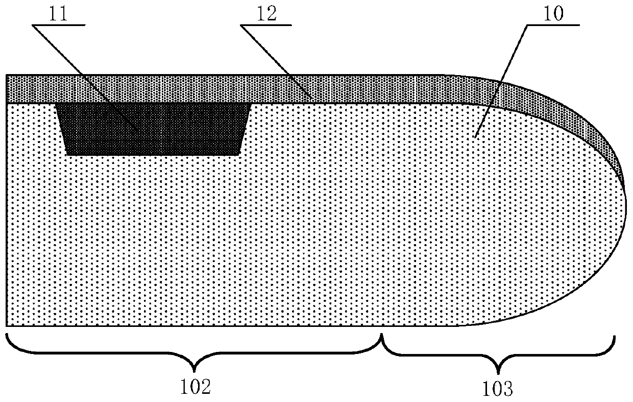
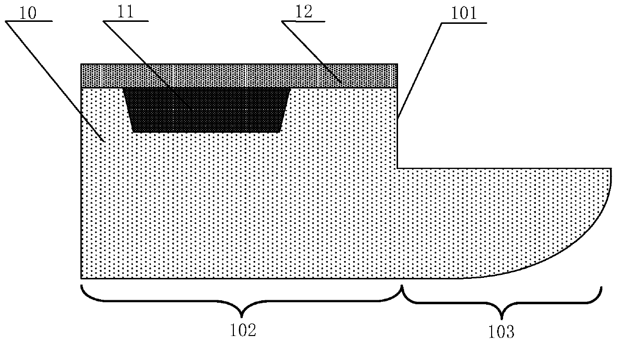
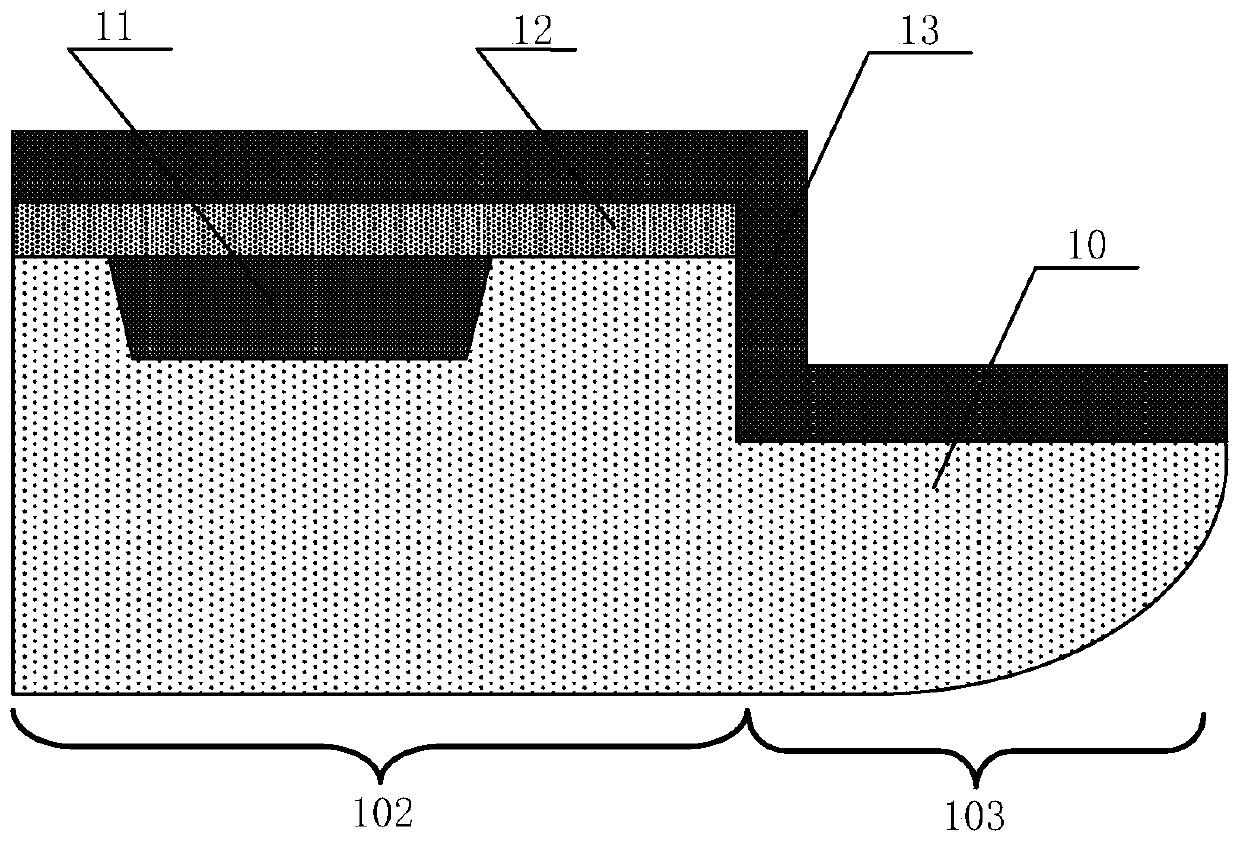
Semiconductor structure and semiconductor process method
A process method and semiconductor technology, applied in the direction of semiconductor devices, semiconductor/solid-state device manufacturing, semiconductor/solid-state device components, etc., can solve problems such as defects, photoresist residue, and affecting product yield, so as to improve yield, The effect of avoiding defects and saving production costs
- Summary
- Abstract
- Description
- Claims
- Application Information
AI Technical Summary
Problems solved by technology
Method used
Image
Examples
Embodiment 1
[0083] see Figure 7 , the present invention provides a kind of semiconductor processing method, described semiconductor processing method comprises the steps:
[0084] 1) Provide wafers;
[0085] 2) forming a dielectric layer on the wafer;
[0086] 3) Etching the dielectric layer to form etching via holes in the dielectric layer;
[0087] 4) forming a metal interconnection layer in the etched via hole;
[0088] 5) forming a protective layer on the upper surface of the dielectric layer and the upper surface of the metal interconnection layer; and
[0089] 6) Perform edge trimming on the wafer.
[0090] In step 1), see Figure 7 Step S1 in and Figure 8 , providing a wafer 20 .
[0091] As an example, the wafer 20 may include a silicon wafer, a germanium (Ge) wafer, a silicon germanium (SiGe) wafer, an SOI (Silicon-on-insulator, silicon-on-insulator) wafer or a GOI (Germanium-on-insulator) wafer. -Insulator, germanium-on-insulator) wafer, etc.; preferably, in this embod...
Embodiment 2
[0131] see Figure 17 , the present invention also provides a semiconductor structure, the semiconductor structure includes: a wafer 20, a dielectric layer 21, the dielectric layer 21 is located on the wafer 20, and an etching through hole 23 is formed in the dielectric layer 21 a metal interconnect layer 24, the metal interconnect layer 24 at least fills the etched via hole 23; and a protective layer 25, the protective layer 25 covers the upper surface of the dielectric layer 21 and the metal interconnect The upper surface of the connecting layer 24.
[0132] As an example, the wafer 20 may include a silicon wafer, a germanium (Ge) wafer, a silicon germanium (SiGe) wafer, an SOI (Silicon-on-insulator, silicon-on-insulator) wafer or a GOI (Germanium-on-insulator) wafer. -Insulator, germanium-on-insulator) wafer, etc.; preferably, in this embodiment, the wafer 20 includes a single crystal silicon wafer.
[0133] As an example, the size of the wafer 20 may be set according to ...
Embodiment 3
[0148] Please combine Figure 2 to Figure 16 refer to Figure 18 , the present invention also provides a semiconductor structure, the semiconductor structure includes: a wafer 20; a dielectric layer 21, the dielectric layer 21 is located on the upper surface of the wafer 20, and an etching via is formed in the dielectric layer 21 hole 23; metal interconnection layer 24, the metal interconnection layer 24 is located in the etched through hole 23; chamfer 204, the chamfer 204 is located in the edge region of the wafer 20, the chamfer 204 After the metal interconnection layer 24 is formed.
[0149] As an example, the wafer 20 may include a silicon wafer, a germanium (Ge) wafer, a silicon germanium (SiGe) wafer, an SOI (Silicon-on-insulator, silicon-on-insulator) wafer or a GOI (Germanium-on-insulator) wafer. -Insulator, germanium-on-insulator) wafer, etc.; preferably, in this embodiment, the wafer 20 includes a single crystal silicon wafer.
[0150] As an example, the size of ...
PUM
 Abstract
Description
Claims
Application Information
 - R&D Engineer
- R&D Manager
- IP Professional
- Industry Leading Data Capabilities
- Powerful AI technology
- Patent DNA Extraction
Browse by: Latest US Patents, China's latest patents, Technical Efficacy Thesaurus, Application Domain, Technology Topic, Popular Technical Reports.
© 2024 PatSnap. All rights reserved.Legal|Privacy policy|Modern Slavery Act Transparency Statement|Sitemap|About US| Contact US: help@patsnap.com


