

Noise elimination structure of compressor and noise elimination method thereof
A compressor and anechoic chamber technology, applied in the field of compressor noise reduction, can solve the problems of small anechoic aperture, limited geometric shape, difficult to find inclusions, etc., and achieve good noise reduction effect
- Summary
- Abstract
- Description
- Claims
- Application Information
AI Technical Summary
Problems solved by technology
Method used
Image


Examples
Embodiment Construction
[0020] The specific implementation manner of the present invention will be described in further detail below by describing the best embodiment with reference to the accompanying drawings.
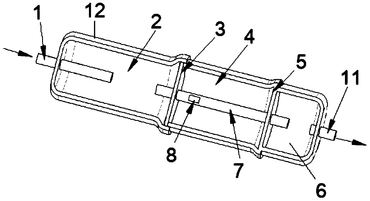
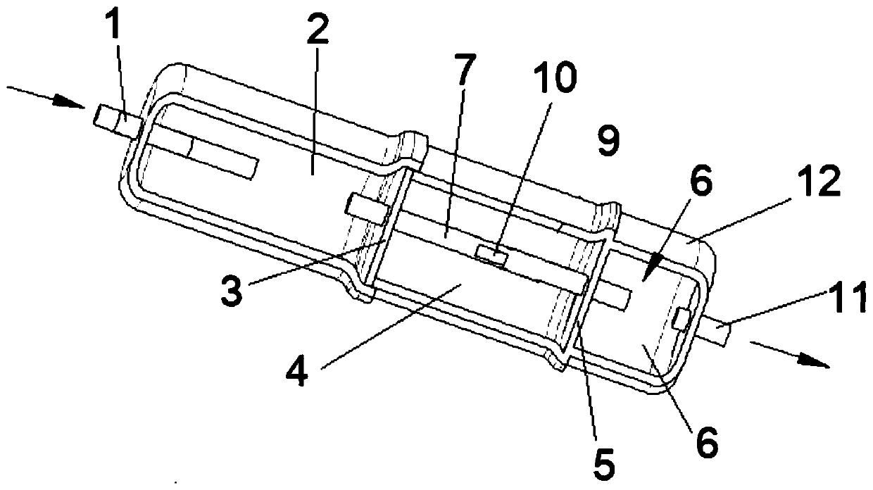
[0021] The arrows in the figure indicate the flow direction of the refrigerant gas.
[0022] Such as figure 1 and figure 2 As shown, the noise reduction structure of this kind of compressor includes a casing 12, and the inside of the casing 12 is provided with a structure that separates the casing 12 into a first noise reduction chamber 2, a second noise reduction chamber 4 and a third noise reduction chamber 6. The first partition 3 and the second partition 5; one end of the housing 12 is provided with an inlet pipe 1 communicating with the first anechoic chamber 2 and the coil of the compressor, and the other end of the housing 12 is provided with a communication with the third anechoic chamber 6 and The outlet pipe 11 of the compressor coil; the first partition 3 and the second partit...
PUM
| Property | Measurement | Unit |
|---|---|---|
| Spacing | aaaaa | aaaaa |
Abstract
Description
Claims
Application Information