Calibration device for quickly positioning collimating lens and calibrating beam pointing

A technology of collimating lenses and calibrating beams, which is applied in the field of laser radar optical system debugging, can solve the problems of not intuitive and convenient operation, inability to cooperate with joint debugging, and limited precision, etc., and achieve intuitive debugging process, light weight and high precision Effect

Pending Publication Date: 2019-08-02
WUHAN UNIV
View PDF4 Cites 0 Cited by
  • Summary
  • Abstract
  • Description
  • Claims
  • Application Information

AI Technical Summary

Problems solved by technology

It is an optional solution to use a thin parallel beam of visible laser (such as helium-neon laser, 632.8nm red light) to calibrate the working angle of the beam guiding element, but this method depends on the subjective judgment of the operator, and the accuracy is limited, and it cannot be directly compared with The mechanical mechanism in the optical system cooperates with the joint adjustment, and the operation is not intuitive and convenient enough

Method used


Image

  • Calibration device for quickly positioning collimating lens and calibrating beam pointing
  • Calibration device for quickly positioning collimating lens and calibrating beam pointing

Examples


Embodiment 1

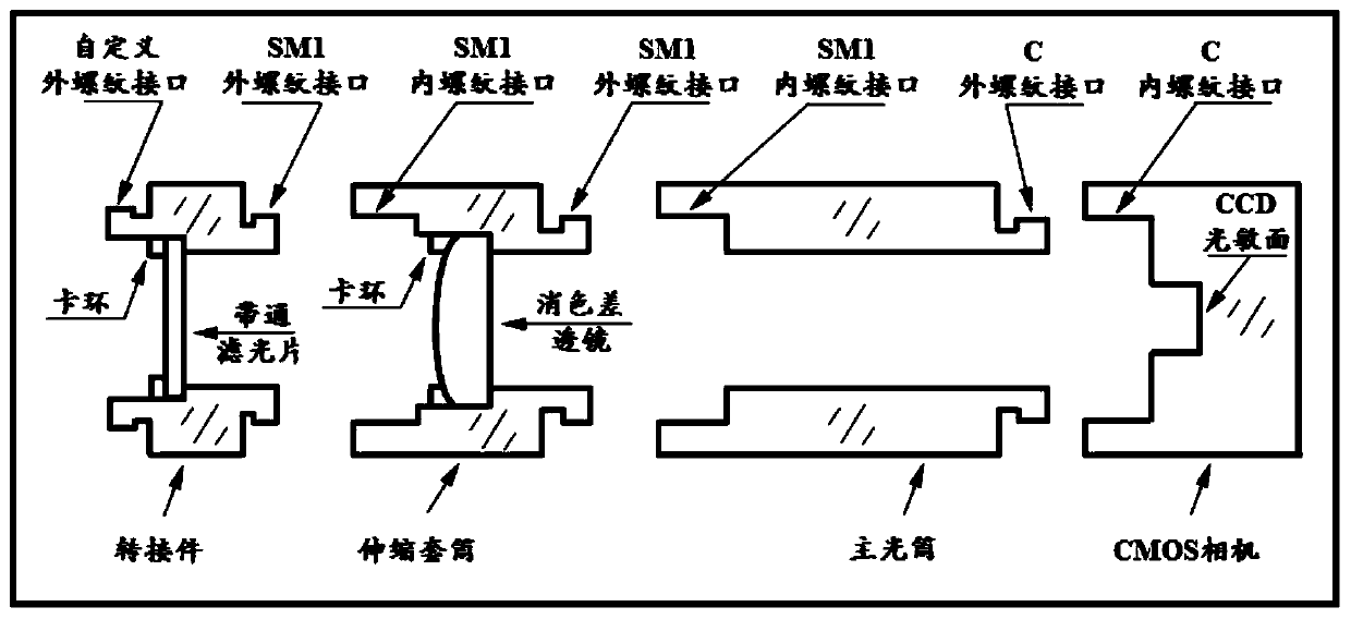
[0031] A calibration device for quickly positioning the collimating lens and calibrating beam pointing provided by the embodiment, including a bandpass filter, an adapter, a telescopic sleeve, an achromatic lens, a main light tube, and a CMOS camera;

[0032] The bandpass filter is used to extract the optical signal in the target spectral band;

[0033] The adapter is used to fix the bandpass filter and quickly access the target optical path to be adjusted;

[0034] The telescopic sleeve is used to fix the achromatic lens;

[0035] The achromatic lens is used for converging the incoming quasi-parallel light signal on the photosensitive surface of the area array CCD of the CMOS camera;

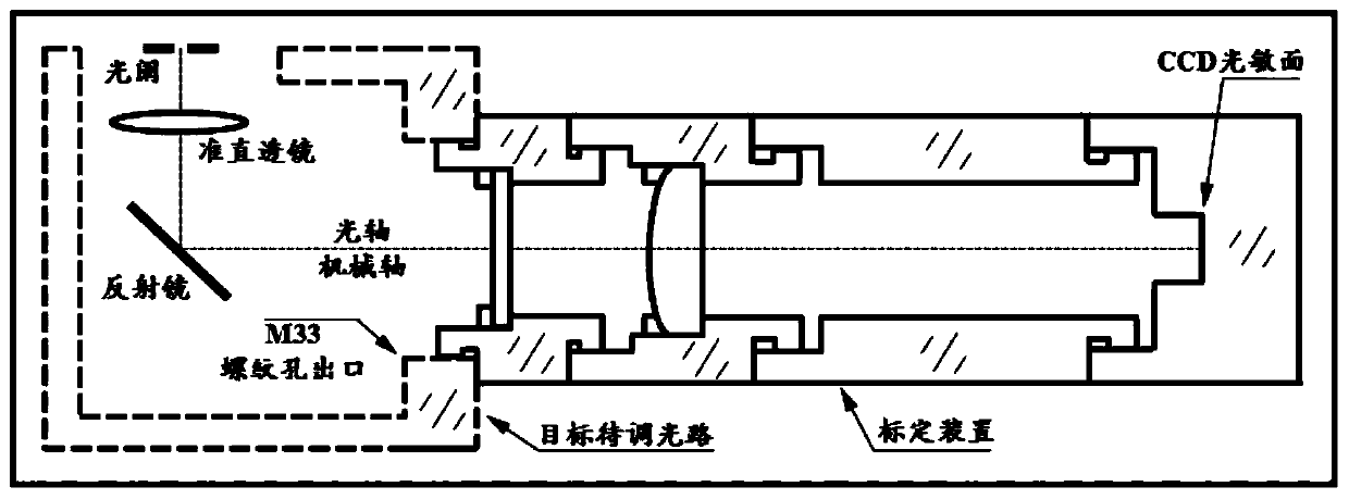
[0036] The main optical tube is used to combine with the telescopic sleeve to ensure that the focal plane of the achromatic lens can coincide with the photosensitive surface of the area array CCD in the CMOS camera;

[0037] The CMOS camera is used for collecting and displaying in real time t...

Embodiment 2

[0055] This embodiment is basically the same as Embodiment 1, the difference is: the central wavelength of the band-pass filter is changed to 355nm; the achromatic lens is selected from the American Thorlabs company ACA254-150-UV model product, and the corresponding focal length of the spectral segment near 355nm is 150mm. For this reason, the present invention can calibrate the position of the collimating lens and the pointing of the light beam working in the ultraviolet band around 355nm.


PUM


Abstract

The invention discloses a calibration device for quickly positioning a collimating lens and calibrating beam pointing. The calibration device comprises a band pass filter, an adapter, a telescopic sleeve, an achromatic lens, a main light tube and a CMOS camera, wherein the band pass filter is configured to extract an optical signal in the target spectral segment; the adapter is configured to fix the band pass filter and fast access the target light path to be dimmed; the telescopic sleeve is configured to fix the achromatic lens; the achromatic lens is configured to concentrate the collimatedparallel optical signals on the surface array CCD photosensitive surface of the CMOS camera; the main light tube is used in combination with the telescopic sleeve to ensure that the focal plane of theachromatic lens can be coincident with the surface array CCD photosensitive surface in the CMOS camera; and the CMOS camera is configured to acquire and real-time display the optical signal patternsconcentrated by the achromatic lens on the surface array CCD photosensitive surface. The calibration device provided by the invention can display the process and result of collimating lens positioningand beam pointing calibration quickly and in real time, and has the advantages such as small volume, light weight, convenient carrying and high precision.

Description

technical field [0001] The invention belongs to the field of lidar optical system debugging, and relates to a portable and visual calibration device capable of quickly and accurately realizing collimator lens positioning and beam pointing calibration. Background technique [0002] Lidar is a powerful tool capable of remote sensing the Earth's atmosphere with high precision and high resolution. During the development and adjustment of the laser radar optical receiving system, it is often required to adjust the optical components or components to the specified working mode to ensure the overall performance of the optical receiving system and the accuracy of the radar target detection parameters. During the assembly and adjustment of optical components, it is necessary to use appropriate tools and methods to assist in the adjustment and ensure the adjustment accuracy. [0003] When developing a miniaturized lidar receiving system, mature medium / small-caliber commercial astrono...

Claims


Application Information

Patent Timeline
Patent Type & Authority Applications(China)
IPC IPC(8): G02B7/00
CPCG02B7/003
Inventor 柳付超易帆张云鹏余长明易洋潘向亮
Owner WUHAN UNIV
Why Eureka
Try Eureka