
Secondary battery current collector and secondary battery using same

A technology for secondary batteries and current collectors, applied in the direction of electrode carriers/collectors, etc., which can solve the problems of increasing battery internal resistance, existing safety risks, and heavy coating weight

Active Publication Date: 2019-08-06
CONTEMPORARY AMPEREX TECH CO
View PDF4 Cites 6 Cited by
  • Summary
  • Abstract
  • Description
  • Claims
  • Application Information

AI Technical Summary

Problems solved by technology

However, the coating layer itself is heavy, which will increase the internal resistance of the battery and affect the battery rate performance. At the same time, it cannot solve the problem that the tab area of ​​the current collector is easy to break, and there are still safety risks.

Method used

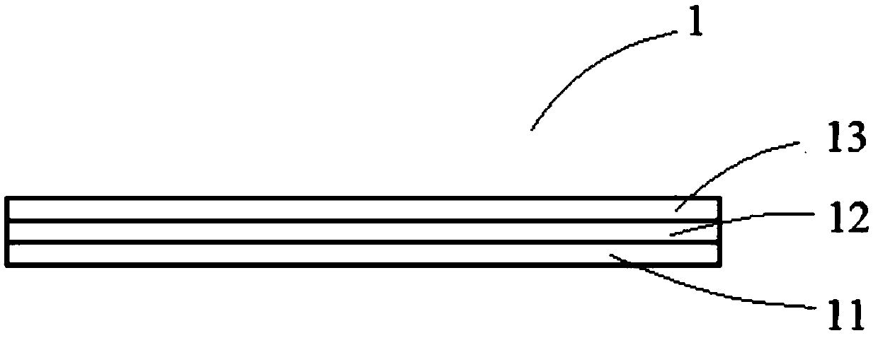
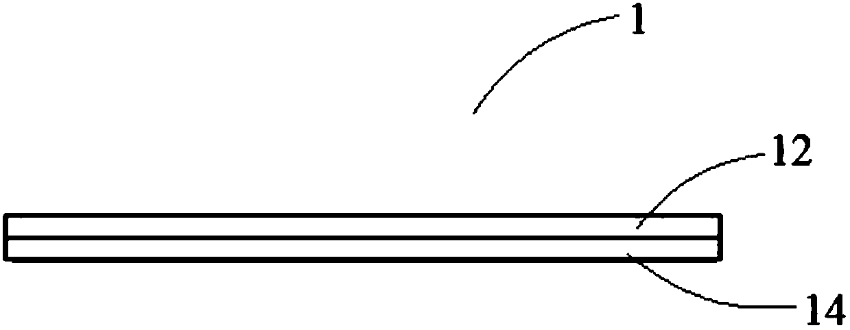

Image

  • Secondary battery current collector and secondary battery using same
  • Secondary battery current collector and secondary battery using same
  • Secondary battery current collector and secondary battery using same

Examples


preparation example Construction

[0060] When the secondary battery is a lithium-ion battery, a conventional lithium-ion battery preparation method can be used, which at least includes the following steps:

[0061] Step 1, coating the coating layer slurry including polymer, inorganic particles and binder on the surface of the positive electrode current collector and / or the negative electrode current collector, and forming a coating layer after drying;

[0062] Step 2, coating the positive electrode slurry including the positive electrode active material, conductive agent and binder on the surface of the positive electrode current collector, forming a positive electrode active material layer after drying, and obtaining the positive electrode sheet;

[0063] Step 3, coating the negative electrode slurry including the negative electrode active material and the binder on the surface of the negative electrode current collector, forming a negative electrode active material layer after drying, and obtaining the negati...

Embodiment 1

[0088] Coating layer preparation

[0089] Mix the polymer, inorganic particles and binder, add water, stir evenly to obtain a coating layer slurry, and then coat the coating layer slurry on the surfaces of both sides of the copper foil of the negative electrode current collector. The coating area includes The current collector body and tabs are dried to obtain coating layers 1-13. The types of polymer, inorganic particles and binder, the mass ratio of the three, the size parameters of polymer and inorganic particles, the thickness of the coating layer, and the pore diameter of the surface and internal micropores of the coating layer are shown in Table 1.

[0090] Positive electrode sheet preparation

[0091] The positive electrode active material NCM433, the conductive agent carbon black, and the binder polyvinylidene fluoride (PVDF) were mixed in a weight ratio of 96:2:2. Add solvent N-methylpyrrolidone, mix and stir evenly to obtain positive electrode slurry. Coat the...


PUM

PropertyMeasurementUnit
Particle sizeaaaaaaaaaa
Diameteraaaaaaaaaa
Thicknessaaaaaaaaaa

Abstract

The application relates to a secondary battery current collector. All or a part of the surface of the current collector is provided with a coating layer containing a polymer, inorganic particles and abinder. Micropores are disposed on the surface of the coating layer and in the coating layer. Since the coating layer contains the polymer and the inorganic particles, a porous net structure can be formed, which supports the surface of the current collector, and ensures the strength of the current collector. When the coating layer is disposed in a tab portion, the problem can be solved that the tab is likely to break and the risk of short circuit occurring in a battery due to the break of the tab can be avoided.

Description

technical field [0001] The present application relates to the field of secondary batteries, in particular, to a current collector of a secondary battery and a secondary battery using the current collector. Background technique [0002] With the popularization of consumer electronic products such as notebook computers, mobile phones, handheld game consoles, tablet computers, etc., people have higher and higher requirements for their batteries, such as requiring batteries to meet small size, light weight, high capacity, and long Cycling and stable performance. Among secondary batteries, lithium-ion secondary batteries have a higher energy density advantage than other types of batteries, and have always occupied a mainstream position in the market. [0003] However, while pursuing high energy density, it is also necessary to take into account the safety performance of the battery. In the actual application process, due to the presence of metal particles in the battery cell or...

Claims


Application Information

Patent Timeline
IPC IPC(8): H01M4/70H01M4/72H01M4/80
CPCH01M4/70H01M4/72H01M4/80Y02E60/10
Inventor 陈仕通王再盛谢斌张盛武龚志杰潘建伟
Owner CONTEMPORARY AMPEREX TECH CO
Learn More