Efficient denitration and dust removal system and method for garbage power plant flue gas

A technology for denitrification and dust removal and power plant, which is applied in the field of high-efficiency denitrification and dust removal system for flue gas in waste-to-energy plants. It can solve problems such as ammonia escape and increased dust content, and achieve the effects of reducing environmental pollution, reducing wear and poisoning, and reducing circulation resistance

Inactive Publication Date: 2019-08-16
凤阳海泰科能源环境管理服务有限公司
View PDF6 Cites 8 Cited by
  • Summary
  • Abstract
  • Description
  • Claims
  • Application Information

AI Technical Summary

Problems solved by technology

[0002] In waste-to-energy plants, in addition to ash that should be specially treated after incineration, the flue gas also contains a large amount of pollutants, which should be specially treated before being discharged into the atmosphere. The main pollutants in the flue gas include soot, SO 2 , HCl, NOx, dioxins (PCDD / PCDF, etc.), heavy metals, etc., and now the NOx concentration for ultra-low emissions is 50mg / m 3 Below, the current ultra-low flue gas denitrification technology in traditional waste-to-energy plants uses selective non-catalytic reduction (SNCR) in the furnace, and high-temperature steam heating (SGH) is used after the desulfurization tower outside the furnace to arrange + selective catalytic reduction ( Selective Catalytic Reduction) SCR device, which requires a large amount of high-quality steam, which is likely to cause ammonia escape and increase the dust content in the flue gas

Method used


Image

  • Efficient denitration and dust removal system and method for garbage power plant flue gas

Examples


Embodiment Construction

[0031] The present invention will be described in further detail below in conjunction with specific examples, but not as a limitation of the present invention.

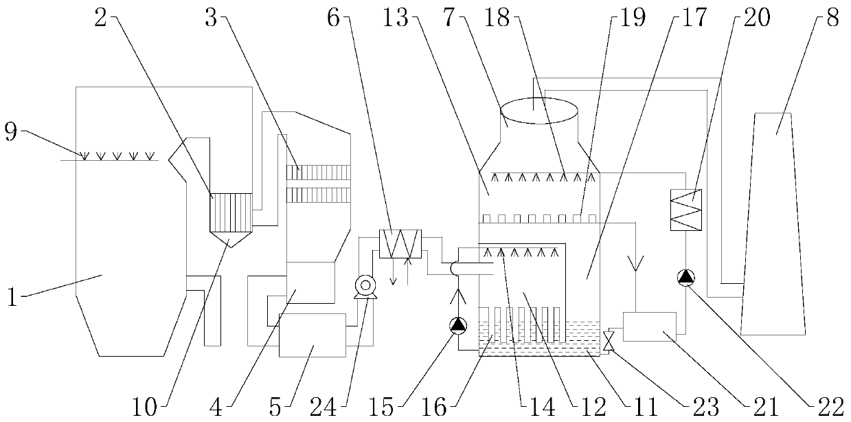
[0032] refer to figure 1 , the high-efficiency flue gas denitrification and dust removal system of a garbage power plant of the present invention includes a waste heat boiler 1, a high-temperature metal dust collector 2, a microporous SCR device 3, an economizer 4, a deacidification device 5, a tubular heat exchanger 6, a wet method tower 7 and chimney 8.

[0033] An SNCR sprayer 9 is installed in the waste heat boiler 1, the exhaust port of the waste heat boiler 1 is connected to the high-temperature metal dust collector 2, and the rear stage of the high-temperature metal dust collector 2 is connected to the microporous SCR The device 3 is connected by pipes, the rear stage of the microporous SCR device 3 is connected with the economizer 4, the rear stage of the economizer 4 is connected with the deacidification dev...


PUM


Abstract

The invention discloses efficient denitration and dust removal system and method for flue gas of a garbage power plant. The dust removal system comprises a waste heat boiler; an SNCR sprayer is mounted in the waste heat boiler and is used for spraying ammonia or urea, so that NOx in the flue gas is primarily reduced, and primary denitration is completed; the high-temperature metal dust remover isused for filtering and intercepting heavy metals, dust and dioxin in the flue gas; the filtered flue gas selectively reacts with NOx under the action of a catalyst through a microporous SCR device togenerate N2 and H2O so as to complete deep denitration; initial deacidification is carried out to the denitrified flue gas in a deacidification device, and deep deacidification and dust removal are carried out in a wet-process tower, thereby achieving ultra-low emission. According to the system and the method, high-temperature dust removal is combined with microporous SCR to deeply remove pollutants such as dust and NOx, so that ultra-low emission is realized. The technology does not need high-temperature steam heating, a large amount of steam can be saved, and the power generation amount is increased.

Description

technical field [0001] The invention belongs to the technical field of environmental protection, and relates to a high-efficiency denitrification and dust removal system and method for flue gas of a garbage power plant. Background technique [0002] In waste-to-energy plants, in addition to ash that should be specially treated after incineration, the flue gas also contains a large amount of pollutants, which should be specially treated before being discharged into the atmosphere. The main pollutants in the flue gas include soot, SO 2 , HCl, NOx, dioxins (PCDD / PCDF, etc.), heavy metals, etc., and now the NOx concentration for ultra-low emissions is 50mg / m 3 Below, the current ultra-low flue gas denitrification technology in traditional waste-to-energy plants uses selective non-catalytic reduction (SNCR) in the furnace, and high-temperature steam heating (SGH) is used after the desulfurization tower outside the furnace to arrange + selective catalytic reduction ( Selective C...

Claims


Application Information

Patent Timeline
Patent Type & Authority Applications(China)
IPC IPC(8): B01D53/75B01D53/79B01D53/86B01D53/68B01D53/56B01D53/50B01D50/00B01D46/54F23G5/46
CPCB01D53/75B01D53/79B01D53/56B01D53/8625B01D46/543B01D53/508B01D53/68B01D53/502F23G5/46B01D2251/2067B01D2251/2062B01D2251/404B01D2251/604B01D2258/0283B01D50/60Y02E20/12
Inventor 何秀锦王军祥李志伟
Owner 凤阳海泰科能源环境管理服务有限公司
Why Eureka
Try Eureka