Method and device for cleaning multi-pollutant flue gas

A technology for cleaning treatment and pollutants, applied in gas treatment, water/sewage multi-stage treatment, neutralized water/sewage treatment, etc., which can solve the problems that limit the popularization and application of activated carbon flue gas control technology, the exhaust gas does not meet the standard, and the use time is short, etc. problems, to achieve the effect of clean recycling, lower investment costs, and reduced usage

Active Publication Date: 2021-10-26
ZHONGYE-CHANGTIAN INT ENG CO LTD
View PDF8 Cites 0 Cited by
  • Summary
  • Abstract
  • Description
  • Claims
  • Application Information

AI Technical Summary

Problems solved by technology

[0005] Although the activated carbon flue gas control technology can realize the coordinated removal of multiple pollutants, in fact, the pollutants are only enriched through adsorption-desorption, and there is a problem of secondary pollution.
For example, the charcoal powder produced in the adsorption and desorption process has not been effectively used, the desorption gas washing wastewater has not been effectively treated, and the high concentration sulfur dioxide flue gas generated after desorption is not up to the standard after the sulfur resource recovery, which seriously limits the activated carbon smoke. Popularization and Application of Gas Control Technology
Due to the relatively short period of industrial use of activated carbon flue gas control technology in China, the above-mentioned problems are relatively new and difficult to deal with. There is no process technology that can be used for reference in the world, and completely independent innovation is urgently needed

Method used


Image

  • Method and device for cleaning multi-pollutant flue gas
  • Method and device for cleaning multi-pollutant flue gas
  • Method and device for cleaning multi-pollutant flue gas

Examples


Embodiment 1

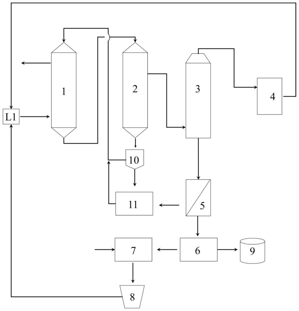
[0115] like image 3 As shown, a multi-pollutant flue gas synergistic governance and wastewater zero emissions or means for the method described in the first embodiment, including flue gas delivery pipes L1, flue gas adsorption device 1, activated carbon hot The regeneration device 2, the wet detergent device 3, the sulfur resource device 4, the acidic filtration device 5, flocculation precipitation device 6. The multi-pollutant flue gas is delivered to the flue gas adsorption device 1 through the flue gas delivery pipe L1. The activated carbon outlet of the flue gas adsorption device 1 is attached to the active carbon thermal regeneration device 2 through the conveying device. The SRG gas outlet of the activated carbon thermal regeneration apparatus 2 is connected to the wet detergent device 3 through the conduit. The high sulfur gase of the wet detergent device 3 is coupled to the sulfur resource device 4. The wastewater outlet of the wet detergent device 3 is connected to the ac...

Embodiment 2

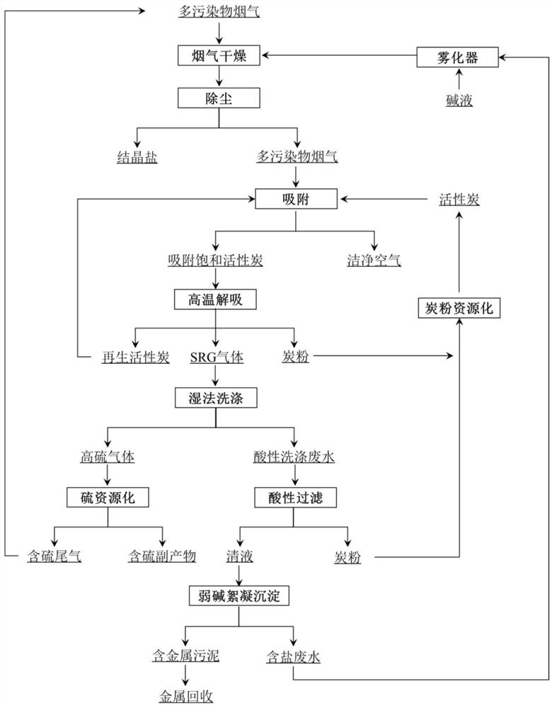
[0117] Example 1 was repeated, but the apparatus further includes an atomizer 7, a dust collector 8, a metal recovery device 9. The liquid outlet of the flocculation precipitation device 6 is coupled to the atomizer 7. The outlet of the atomizer 7 is connected to the dust collector 8. The dust collector 8 is disposed on the flue gas delivery conduit L1. The atomizer 7 is provided with an alkali inlet. The solid outlet of the flocculation precipitation device 6 is coupled to the metal recovery device 9. The apparatus also includes a screening device 10, a carbon powder resource device 11. The activated carbon exit of the activated carbon thermal regeneration apparatus 2 is coupled to the screening device 10. The large particulate activated carbon outlet of the screening device 10 is coupled to the flue gas adsorption device 1. The small particulate activated carbon outlet of the sieve device 10, the solid outlet of the acidic filtration device 5 is coupled to the carbon powder reso...

Embodiment 3

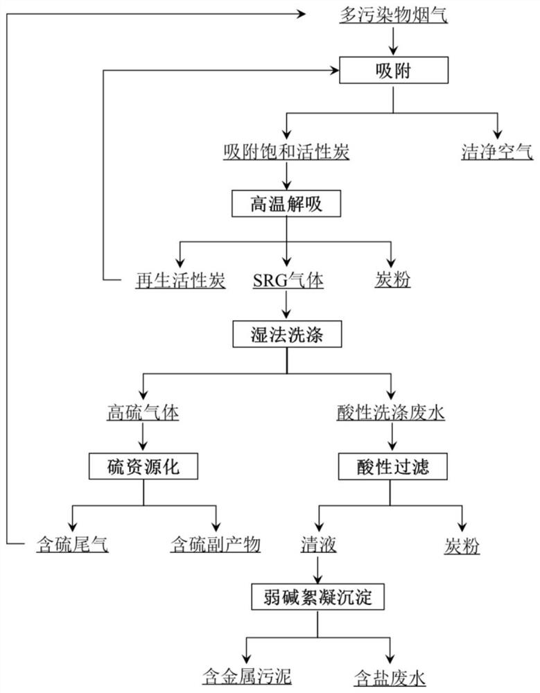
[0119] like figure 1 As shown, a multi-pollutant flue gas cleaning treatment method, the method includes the following steps:

[0120] 1) Adsorption of multi-pollutant flue gas: Transfer multi-pollutant flue gas to the flue gas adsorption device 1 through the flue gas delivery pipe L1, and the flue gas adsorption device 1 has activated carbon, and the multi-pollutant flue gas uses activated carbon with eruption adsorption. Treatment, adsorb saturated activated carbon;

[0121] 2) Thermal regeneration of activated carbon: transports adsorption saturated activated carbon to the activated carbon thermal regeneration apparatus 2. The adsorption saturated activated carbon is heated to 400 ° C for heat and regeneration;

[0122] 3) Treatment of the SRG gas: The SRG gas produced by the activated carbon thermal regeneration is wetly washed by the wet detergent device 3, and the solution used by the wet washing is dilute, the pH is 5; the volume flow ratio of SRG gas and dilute sulfuric ac...


PUM

PropertyMeasurementUnit
particle diameteraaaaaaaaaa

Abstract

A method for cleaning, treating and disposing of multi-pollutant flue gas, the method comprising the following steps: 1) adsorption of multi-pollutant flue gas: treating multi-pollutant flue gas with activated carbon to obtain adsorbed saturated activated carbon; 2) thermal regeneration of activated carbon: adsorbing Saturated activated carbon is heated to high temperature for thermal regeneration; 3) SRG gas treatment: SRG gas generated by thermal regeneration of activated carbon is wet-washed to obtain high-sulfur gas and acidic scrubbing wastewater; 4) High-sulfur gas treatment: the high-sulfur gas obtained in step 3) Sulfur gas recovers sulfur resources through the sulfur resource process; 5) Acidic washing wastewater treatment: the acidic washing wastewater obtained in step 3) is filtered through acid to obtain clear liquid and carbon powder; 6) clear liquid flocculation: obtained in step 5) Alkali is added to the clear liquid to make the clear liquid flocculate and precipitate to obtain metal-containing sludge and salt-containing wastewater. By adopting the method of the invention, secondary pollutants can be well treated, wastes can be turned into treasures, reused, costs can be saved, resources can be recycled, and the environment can be protected.

Description

Technical field [0001] The present invention relates to a multi-pollutant flue gas treatment method, and more particularly to a multi-pollutant flue gas cleaning treatment method and a device thereof. It belongs to the field of resource environmental protection. Background technique [0002] In conventional steel, electricity, colored, petrochemical, chemical or building materials, often produce a variety of pollutants, such as SO due to many types of raw materials used. 2 , NOx, dust, VOCS, heavy metals, etc. As the national environmental laws and standards are more strict, except for major pollutants, it has gradually been strictly limited to the emissions of various secondary pollutants. For example, the National Environmental Protection Department issued the implementation of "Iron and Steel Sintering, Pollutant Emission Standards" (GB28662-2012) in 2012 (GB28662-2012) increased NOx, dioxin contaminants, and fluoride emission standards. This makes the flue gas governance tech...

Claims


Application Information

Patent Timeline
Patent Type & Authority Patents(China)
IPC IPC(8): B01D53/86B01D53/50B01D53/56B01D53/70B01D46/02C02F9/10
CPCB01D46/02B01D53/02B01D53/18B01D53/50B01D53/8625B01D53/8662B01D2253/102B01D2255/702B01D2258/0283B01D2259/40088C02F1/001C02F1/04C02F1/52C02F1/66C02F9/00C02F2001/007
Inventor 叶恒棣魏进超杨本涛刘昌齐
Owner ZHONGYE-CHANGTIAN INT ENG CO LTD
Why Eureka
Try Eureka