Carbon dioxide capturing system and method based on waste heat recycling of turbine exhaust steam

A waste heat recovery and carbon dioxide technology, applied in chemical instruments and methods, separation methods, indirect heat exchangers, etc., can solve the problems of insufficient recovery and utilization of heat flow energy, waste of heat energy, etc., to improve steam utilization rate and power generation efficiency, The effect of high energy efficiency utilization and reduction of cooling water consumption

Active Publication Date: 2019-08-23
CHONGQING UNIV
View PDF4 Cites 11 Cited by
  • Summary
  • Abstract
  • Description
  • Claims
  • Application Information

AI Technical Summary

Problems solved by technology

At the same time, there are still many heat flow energy in the carbon capture system that has not been fully recovered, resulting in a great waste of heat energy

Method used


Image

  • Carbon dioxide capturing system and method based on waste heat recycling of turbine exhaust steam
  • Carbon dioxide capturing system and method based on waste heat recycling of turbine exhaust steam

Examples


Embodiment 1

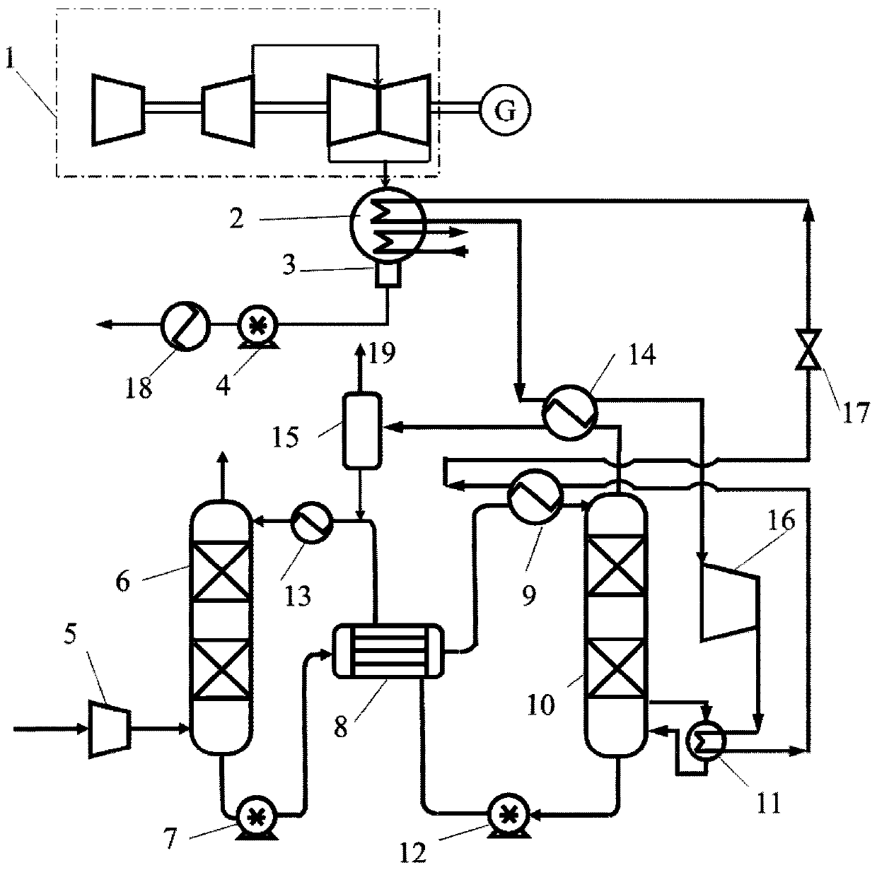
[0018] Example 1, see figure 1 , a carbon dioxide capture system based on steam turbine exhaust heat recovery and utilization, including a carbon dioxide capture subsystem and a heat pump subsystem based on steam turbine exhaust heat recovery;

[0019] The carbon dioxide capture subsystem includes an induced draft fan 5, an absorption tower 6, a rich liquid pump 7, a lean / rich liquid heat exchanger 8, a rich liquid heat exchanger 9, a desorption tower 10, a reboiler 11, and a lean liquid pump 12 , lean liquid cooler 13, tower top gas heat exchanger 14 and gas-liquid separator 15.

[0020] The heat pump subsystem based on steam turbine exhaust heat recovery includes a condenser 2 , an overhead gas heat exchanger 14 , a compressor 16 , a reboiler 11 , a rich liquid heat exchanger 9 and a throttle valve 17 .

[0021] In the carbon dioxide capture subsystem, the absorption tower 6 has a bottom gas inlet for the CO-containing gas introduced through the induced draft fan 5. 2 The ...

Embodiment 2

[0029] Embodiment 2, a carbon dioxide capture method based on the recovery and utilization of waste heat from steam turbine exhaust, comprising the following steps: externally purified CO-containing 2 After the flue gas is pressurized by the induced draft fan 5, it enters the absorption tower 6 from the gas inlet at the bottom of the absorption tower 6, and contacts with the lean liquid entering from the liquid inlet at the top of the absorption tower in countercurrent, and the lean liquid absorbs the carbon dioxide in the flue gas and becomes a rich liquid, which is processed The final flue gas is sent from the top gas outlet to the subsequent delivery pipeline; the rich liquid flows out from the liquid outlet at the bottom of the absorption tower, and is boosted by the rich liquid pump 7 to enter the lean / rich liquid heat exchanger 8 and the high-temperature CO 2 The absorbent performs heat exchange, recovers the heat of the high-temperature lean liquid from the lean liquid p...


PUM


Abstract

The invention discloses a carbon dioxide capturing system and method based on waste heat recycling of turbine exhaust steam. The carbon dioxide capturing system based on waste heat recycling of turbine exhaust steam comprises a carbon dioxide collecting sub-system and a waste heat recycling heat pump sub-system based on turbine exhaust steam, wherein the carbon dioxide collecting sub-system comprises an induced draft fan, an absorption tower, a rich liquid pump, a barren / rich liquid heat exchanger, a rich liquid heat exchanger, a desorption tower, a reboiler, a barren liquid pump, a barren liquid cooler, a tower top gas heat exchanger and a gas-liquid separator; the waste heat recycling heat pump subsystem based on turbine exhaust steam comprises a condenser, a tower top gas heat exchanger, a compressor, a reboiler, a barren / rich heat exchanger and a throttling valve; and in the carbon dioxide collecting sub-system, the absorption tower is provided with a bottom gas inlet used for enabling CO2-containing flue gas introduced by the induced draft fan to enter the adsorption tower, and a bottom liquid outlet is connected with an inlet of the rich liquid pump. The system and method provided by the invention are suitable for trapping low-concentration CO2 in flue gas generated by coal-fired power plants and the like.

Description

technical field [0001] The invention relates to a carbon dioxide capture system and method, in particular to a carbon dioxide capture system and method based on recovery and utilization of waste heat from steam turbine exhaust. Background technique [0002] In order to meet the ever-growing energy demand of the society, the combustion of a large amount of fossil fuels such as coal and natural gas leads to CO 2 The massive emission of gas has brought serious greenhouse effect and climate change, which has aroused the widespread concern of all mankind. Therefore, efficient and economical carbon dioxide capture technology is very necessary. [0003] At present, the carbon dioxide post-combustion capture technology using alkaline alcohol amine aqueous solution as the chemical absorbent is relatively mature, and relevant demonstration projects have begun in the power industry. However, in order to realize the regeneration of the absorbent and the desorption of carbon dioxide in...

Claims


Application Information

Patent Timeline
Patent Type & Authority Applications(China)
IPC IPC(8): B01D53/96B01D53/62B01D53/78F28D7/00F28D7/16
CPCB01D53/343B01D53/62B01D53/78B01D53/96B01D2251/80B01D2257/504B01D2258/0283F28D7/00F28D7/16Y02A50/20Y02C20/40
Inventor 丁玉栋郭李恒廖强朱恂王宏程旻何雪丰
Owner CHONGQING UNIV
Why Eureka
Try Eureka