Supercharge Your Innovation With Domain-Expert AI Agents!

Electric locomotive pantograph type current collector head of multi-ring structure

An electric locomotive, multi-ring structure technology, applied in the field of rail transit, can solve the problems of airway damage, increase the flow of the sliding plate and the contact line, instability, etc., so as to reduce the probability of arcing and efficiently fit the contact line. , The effect of stable flow effect

Pending Publication Date: 2019-08-23
SOUTHWEST JIAOTONG UNIV
View PDF0 Cites 2 Cited by
  • Summary
  • Abstract
  • Description
  • Claims
  • Application Information

AI Technical Summary

Problems solved by technology

However, there are still the following problems: (1) Insufficient utilization of carbon skateboard materials (there are unworn areas of carbon skateboards at both ends of the "non-sweet spot" of carbon skateboards, resulting in waste of carbon skateboard materials); (2) carbon skateboards During the high-speed operation of the train, the damage is serious and the life is limited (under the high-speed operation of the train, the flexible friction between the carbon skateboard and the contact wire at low speed gradually evolves into a rigid impact between the contact wire and the carbon skateboard, and the rigid impact is easy to cause the carbon skateboard to appear (3) Poor contact between the carbon skateboard and the contact wire (increased offline rate) will cause unstable flow between the skateboard and the contact wire, resulting in frequent arcing, which will cause ablation on the surface and interior of the skateboard; (4 ) The front and rear double bow structure has poor aerodynamic performance and large wind resistance
(5) The number of pantograph slides supported by the traditional pantograph head is fixed, so it is difficult to effectively and flexibly adapt to the changing traction power
The pantograph and carbon skateboard mainly need to deal with the following challenges under the high-speed operation of the train: First, the frictional heat generated by the high-speed relative friction between the train and the carbon skateboard will increase with the increase of the speed of the train. The heat dissipation performance of the carbon skateboard will face huge challenges; (1) When the train speed increases, the severe mechanical impact of the carbon skateboard when it passes through the "hard point" on the contact net (the place where the contact line card hangs the contact wire) will cause the skateboard to collapse (2) The poor contact between the carbon slide plate and the contact wire also intensifies as the train speed increases, and the increase in the off-line rate directly leads to frequent arcing, and the high temperature generated by the arc will further burn the already damaged (3) In a high-speed train, if the carbon skateboard is seriously damaged and touches the pre-buried air passage between the carbon skateboard and the skateboard bracket, the damage to the air passage will cause the pantograph to lower its bow. , the train stops; (4) The load of the train often changes between light load and heavy load, and the traditional double slide or single slide structure is difficult to adapt to the changing train load
[0006] Due to the structural design of the above-mentioned traditional pantograph head, there are problems such as insufficient utilization of carbon slide material, short life of carbon slide, serious damage at high speed, unstable flow, and difficulty in adapting to large changes in traction power.

Method used


Image

  • Electric locomotive pantograph type current collector head of multi-ring structure
  • Electric locomotive pantograph type current collector head of multi-ring structure
  • Electric locomotive pantograph type current collector head of multi-ring structure

Examples


Embodiment Construction

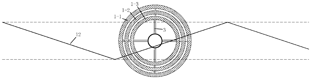
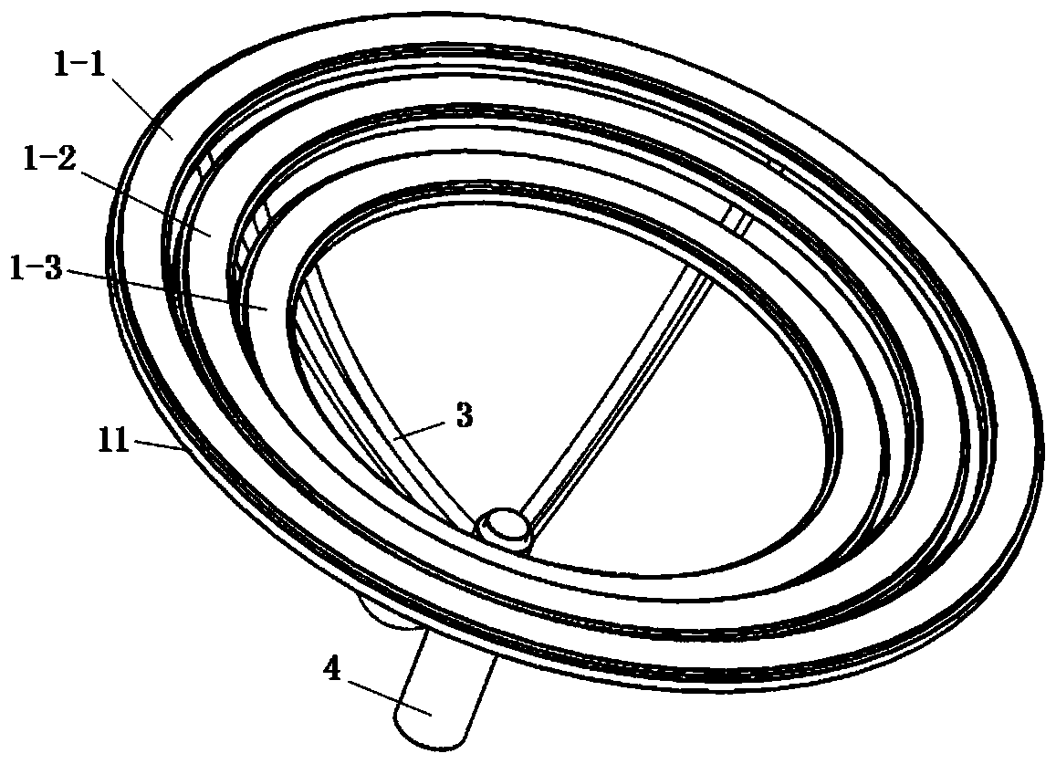
[0030] figure 1 , figure 2 , image 3 , Figure 4 , Figure 5 It shows a pantograph head of an electric locomotive with multi-ring structure, and the circular rotating disk 8-1 and the disk-shaped insulating base 8-2 in it form a rotational fit relationship through balls 8-3 The structure of the support arm base 4 is: the lower part of the inner cylinder 4-1 is movable in the middle cylinder 4-2, the lower part of the middle cylinder 4-2 is movable in the outer cylinder 4-1, and the inner cylinder and the middle There is an inner cylinder lifting structure 9 between the cylinders: two gears 13 driven by motors are rotatably installed in the middle cylinder, one on the left and one on the right. Two rows of ring-shaped tooth protrusions 14 are meshed, the above-mentioned motor is installed in the middle barrel through the motor seat, the motor seat is fixed on the inner wall of the middle barrel, the motor shaft is connected with one end of the gear 13 shaft through a coup...


PUM


Abstract

Provided is an electric locomotive pantograph type current collector head of a multi-ring structure. A rotary disc sleeves an insulation base through balls, and an inner barrel lifting structure is arranged between an inner barrel and a middle barrel. Two gears driven by motors correspondingly are mounted in the middle barrel, and the two gears are engaged with two columns of annular tooth protrusions on the outside of the inner barrel. A middle barrel lifting structure between the middle barrel and an outer barrel is the same as the inner barrel lifting structure. The bottom of the outer barrel is fixed to the rotary disc, four supporting arms are fixed to each of the outer barrel, the middle barrel and the inner barrel, and an annular carbon contact strip is mounted on each supporting arm through an annular bracket. A plurality of springs are fixed to a current receiving conductor fixed to the insulation base, and an annular electric brush fixed into the outer barrel is in contact with the springs. Current of the current receiving conductor is guided out to car-mounted electric equipment through a wire. The electric locomotive pantograph type current collector head has the advantages of improving the utilization rate of contact strip materials, prolonging the service life, improving the current receiving stability, reducing air resistance and the like.

Description

technical field [0001] The invention relates to the technical field of rail transit, in particular to a multi-ring structure pantograph head of an electric traction locomotive. Background technique [0002] Electric traction locomotives usually receive current in the pantograph-catenary mode, which is the pantograph and catenary. The pantograph is installed on the top of the train, and the catenary is suspended above the roof through the tower along the line, and the electric energy is transmitted by the catenary wire in the catenary. The carbon sliding plate of the pantograph head on the top of the train is in contact with the contact wire, and the electric energy on the contact wire is transmitted to the on-board electric traction equipment and weak current equipment through the pantograph. The pantograph-catenary system is the key to the stable power transmission of the train. [0003] The pantograph-catenary carbon skateboard is the key consumable in the pantograph-cate...

Claims


Application Information

Patent Timeline
IPC IPC(8): B60L5/20
CPCB60L5/205
Inventor 肖嵩吴京驰饶阳罗远培张灿
Owner SOUTHWEST JIAOTONG UNIV
Features
  • R&D
  • Intellectual Property
  • Life Sciences
  • Materials
  • Tech Scout
  • Unparalleled Data Quality
  • Higher Quality Content
  • 60% Fewer Hallucinations
Learn More