Tail gas dehydrogenation device for fuel cell automobile

A fuel cell and vehicle exhaust technology, which is applied in battery/fuel cell control devices, fuel cells, electric vehicles, etc., can solve the problems of inconvenient installation and disassembly of devices, complicated adjustment and control, and large fluctuations in hydrogen concentration, so as to reduce potential impacts. and hazards, easy installation and disassembly, and small footprint

Pending Publication Date: 2019-08-23
北京佳安氢源科技股份有限公司
View PDF0 Cites 2 Cited by
  • Summary
  • Abstract
  • Description
  • Claims
  • Application Information

AI Technical Summary

Problems solved by technology

[0006] At present, in response to the above problems, the industry adopts two technical routes to deal with them. The first one is to inject a large amount of air into the exhaust gas to dilute the hydrogen in it so that it is discharged below the lower limit of explosive concentration. Intermittent discharge, and the concentration of hydrogen in the exhaust gas fluctuates greatly, so it is necessary to start and stop the air injection fan in real time, and adjust the air injection volume in real time, and the adjustment control is more complicated
The second is to use a reaction catalyst to make hydrogen react to generate water and then discharge it. However, the system integration degree of this method is not high, and there are many inconveniences in practical applications, such as inconvenient installation and disassembly of the device, low catalyst activity at low temperatures, and catalyst It is inconvenient to replace, and more importantly, the air mixing system in the catalytic reaction is not adaptable

Method used


Image

  • Tail gas dehydrogenation device for fuel cell automobile
  • Tail gas dehydrogenation device for fuel cell automobile
  • Tail gas dehydrogenation device for fuel cell automobile

Examples


Embodiment Construction

[0023] The present invention will be further described below in conjunction with accompanying drawing:

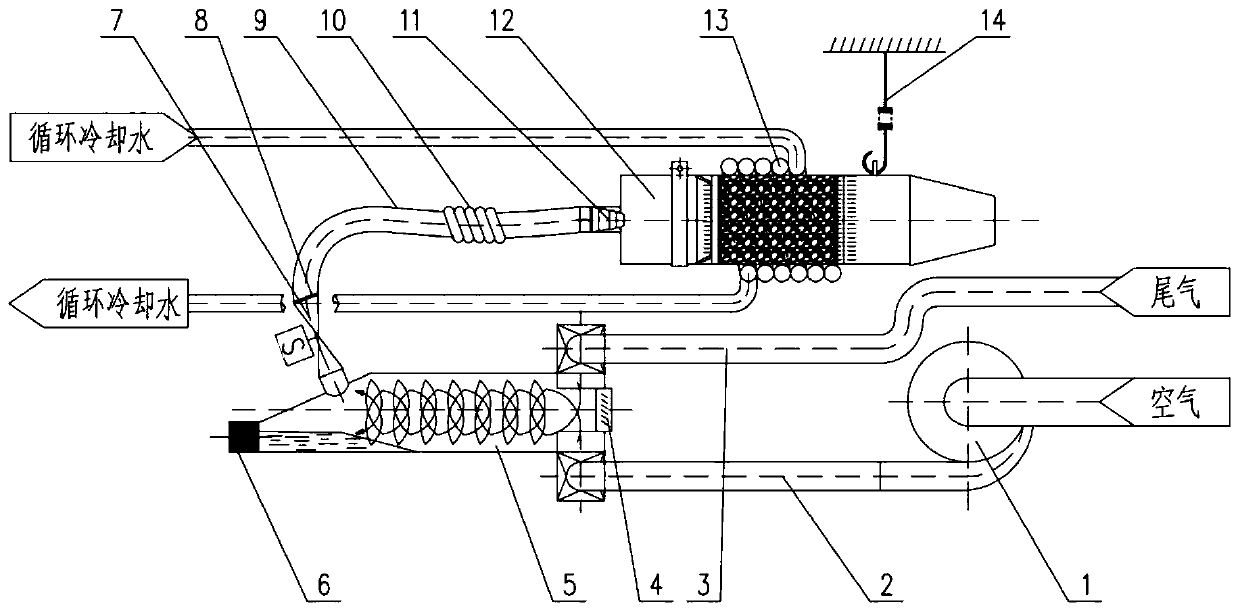
[0024] The overall structure of a fuel cell vehicle tail gas dehydrogenation device of the present invention is shown in figure 1 , including a cyclone separator 5, a burst disc 4, a solenoid valve 7, an air pipe 2, an intake fan 1, a hose 9, and a catalytic converter 12. The system includes exhaust gas collection, separation, buffering, air injection, and mixing. The catalytic converter 12 equipped with a catalyst is connected to the catalytic converter 12 with a soft connection quick joint 11 that is easy to install and disassemble, so as to realize exhaust gas collection, steam-water separation, injection of air dilution, and catalytic reaction, so that the hydrogen in the exhaust gas of the fuel cell vehicle can be safely discharged after generating water, and the system is integrated High strength, easy to disassemble.

[0025] The exhaust pipe 3 used to receive the f...


PUM


Abstract

The utility model relates to a tail gas dehydrogenation device for a fuel cell automobile, and belongs to a purification treatment device. The device is used for purifying fuel cell hydrogen tail gas.The device comprises a tail gas pipe, a gas pipe, a cyclone separator and a catalyst, wherein the cyclone separator is connected with the catalyst through a hose, the tail gas pipe is connected to agas inlet at one end of the cyclone separator, and the gas pipe is connected with a bottom gas inlet of the cyclone separator; an electromagnetic valve is arranged between the hose and the cyclone separator; when the pressure in the cyclone separator reaches a set value, the electromagnetic valve is automatically opened; the catalyst arranged in the catalyst is used for carrying out catalytic reaction on oxygen and hydrogen to generate water, so that the purpose of safe discharge is achieved. The invention has the beneficial effects that the device can guarantee that the hydrogen-containing tail gas discharged by a fuel cell system is safely purified and treated in a catalytic reaction mode, and reduces the potential influence and harm possibly caused to the atmosphere and the environmentdue to hydrogen emission. The device is high in system integration level, small in occupied space and convenient to mount and dismount.

Description

technical field [0001] The invention belongs to a purification treatment device, which is used for the purification treatment of the hydrogen tail gas of a fuel cell. Background technique [0002] Fuel cell is the fourth-generation power generation technology after hydropower, thermal power and atomic power generation. It is also the only power device with pollution-free, high-efficiency, wide application, no noise and continuous work. It is considered to be the most promising power plant in the 21st century. High-efficiency and clean power generation technology with promising development prospects. Compared with the three new energy industries of biofuel, wind power and solar energy, the current market scale of fuel cells is still small. [0003] At present, the application of fuel cells is mainly concentrated in three fields: the application of fuel cells in motor vehicles, the application of fuel cells in portable equipment, and the application of fuel cells in stationar...

Claims


Application Information

Patent Timeline
Patent Type & Authority Applications(China)
IPC IPC(8): H01M8/0662B01D53/24B01D53/86B60L58/30
CPCB01D53/24B01D53/86B01D2257/108B60L58/30H01M8/0662Y02E60/50Y02T90/40
Inventor 李世刚马凤坤荣杰
Owner 北京佳安氢源科技股份有限公司
Why Eureka
Try Eureka