Novel hybrid beam forming structure of millimeter wave MU-MISO system and setting method

A hybrid beam, digital beamforming technology, applied in transmission systems, radio transmission systems, diversity/multi-antenna systems, etc., to reduce energy consumption, improve system performance, and compensate for performance losses

Active Publication Date: 2019-08-23
DALIAN UNIV OF TECH
View PDF4 Cites 15 Cited by
  • Summary
  • Abstract
  • Description
  • Claims
  • Application Information

AI Technical Summary

Problems solved by technology

However, the problems caused by low-resolution phase shifters in par

Method used


Image

  • Novel hybrid beam forming structure of millimeter wave MU-MISO system and setting method
  • Novel hybrid beam forming structure of millimeter wave MU-MISO system and setting method
  • Novel hybrid beam forming structure of millimeter wave MU-MISO system and setting method

Examples


Embodiment 1

[0057] Embodiment 1: Millimeter wave channel modeling based on a uniform planar array.

[0058] Due to the highly concentrated transmission characteristics of the millimeter wave band, the millimeter wave channel can be simply described as the sum of multiple transmission paths. For the millimeter wave MU-MISO system, the channel vector between the base station and the kth user can be expressed as:

[0059]

[0060] The first item in the formula is the normalization coefficient, L k Indicates the number of channel paths of the kth user, α k,l Indicates the gain of the lth path in the kth channel vector. a(φ k,l ,θ k,l ) represents the transmission steering vector, and the angles of departure (Angle of Departure, AoD) in the horizontal and vertical directions are φ k,l and θ k,l . For dimension N t =N x ×N y , a uniform planar array with antenna spacing d, the steering vector can be expressed as:

[0061]

[0062] In the formula is the Kronecker product opera...

Embodiment 2

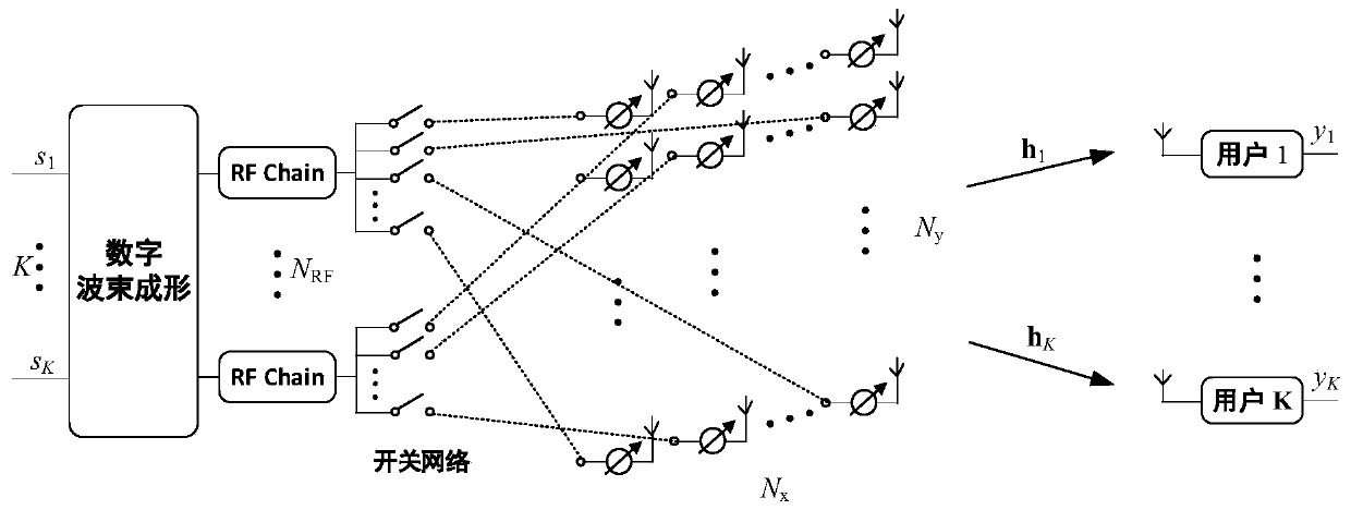
[0066] Embodiment 2: Hybrid beamforming design based on a novel dynamic sub-array structure.

[0067] Let the simulated beamforming matrix be When the k-th RF chain is connected to the i-th antenna through a low-resolution phase shifter, the corresponding position in the analog beamforming matrix takes a non-zero value, namely Otherwise F RF (i,k)=0. In order to ensure that there is no overlap between different subarrays, each row of the analog beamforming matrix has only one non-zero entry, ie ||F RF (i,:)|| 0 =1,i=1,...,N t . Then, the transmission signal at the base station can be expressed as:

[0068]

[0069] In the formula, s k ,k=1,...,K, are symbols transmitted to the kth user. All information symbols are independent of each other and have Considering a narrowband system, the received signal of the kth user can be expressed as:

[0070]

[0071] means h k ,k=1,...,K represents the channel vector between the base station and the kth user, is indepe...


PUM


Abstract

The invention provides a novel hybrid beam forming structure of a millimeter wave MU-MISO system and a setting method. The structure comprises a digital beam former for processing the amplitude and the phase of a signal in a baseband, a plurality of radio frequency chains for performing frequency conversion on the signal, and an analog beam former for performing phase modulation on the radio frequency signal. The method comprises: a sending signal being firstly subjected to digital beam forming on a baseband through the digital beam former, and then being subjected to up-conversion through theradio frequency chain to obtain an analog signal; finally, completing analog beamforming. According to the structure and the method, a low-energy-consumption low-resolution phase shifter and a simpleswitch network are used to realize a dynamic sub-array structure. While the energy consumption is effectively reduced, flexible diversity of a millimeter wave large-scale antenna and multiple users is utilized to compensate performance loss caused by a low-resolution phase shifter and a fixed sub-array, and win-win of system energy efficiency and spectrum efficiency is realized.

Description

technical field [0001] The present invention relates to the technical field of wireless communication, in particular to a novel hybrid beamforming structure and setting method of a millimeter wave MU-MISO system. Background technique [0002] Millimeter wave communication is considered to be one of the key technologies in the 5G network because of its ability to provide gigahertz frequency bandwidth and high transmission rate. Due to the small size of the antenna in the mmWave frequency band, a large-scale antenna array can be packaged in a small area. This feature makes it possible to use large-scale multi-antenna arrays in mmWave systems, thereby providing sufficient beamforming gain to compensate for the severe path loss of mmWave channels. However, it is not easy to implement beamforming for large-scale antenna arrays in mmWave systems. Considering the cost and power consumption of hardware devices, the traditional all-digital beamforming architecture cannot be practic...

Claims


Application Information

Patent Timeline
IPC IPC(8): H04B7/06
CPCH04B7/0617Y02D30/70
Inventor 李明李宏宇刘倩
Owner DALIAN UNIV OF TECH
Why Eureka
Try Eureka