Non-contact method for stripping optical fiber coating layer

A non-contact, coating technology, applied in the field of optical fibers, can solve the problems of inconvenient length control of stripping, difficult cleaning of corrosive liquid, residues, etc., so as to save the ultrasonic cleaning process, and will not cause physical damage, wear and tear. short time effect

Inactive Publication Date: 2019-08-30
广州奥鑫通讯设备有限公司
View PDF4 Cites 0 Cited by
  • Summary
  • Abstract
  • Description
  • Claims
  • Application Information

AI Technical Summary

Problems solved by technology

[0008] Technical disadvantages of metal pliers: (1) Because the V-shaped blade is quenched and tempered, it has high hardness. During the process of peeling off the coating layer, the probability of damage to the cladding surface and even the fiber core is relatively high, resulting in a The force level is low; (2) With the long-term use of metal pliers, the V-shaped blade wears and becomes blunt, and the positioning screw frequently presses against the pliers handle. The positioning screw and pliers handle will be worn and deformed. Scrapped metal pliers, the service life is not long; (3) After long-term use, the blade, positioning screw and clamp handle are worn and deformed, making the positioning accuracy of the blade lower and unstable, which will further increase the damage probability of the optical fiber cladding and fiber core ; The above shortcomings will increase the quality risk of optical fiber communication device products without light
[0009] The technical disadvantages of thermal stripping pliers: (1) This technology belongs to the design of mechatronics, with high degree of automation...

Method used


Image

  • Non-contact method for stripping optical fiber coating layer
  • Non-contact method for stripping optical fiber coating layer

Examples


Embodiment Construction

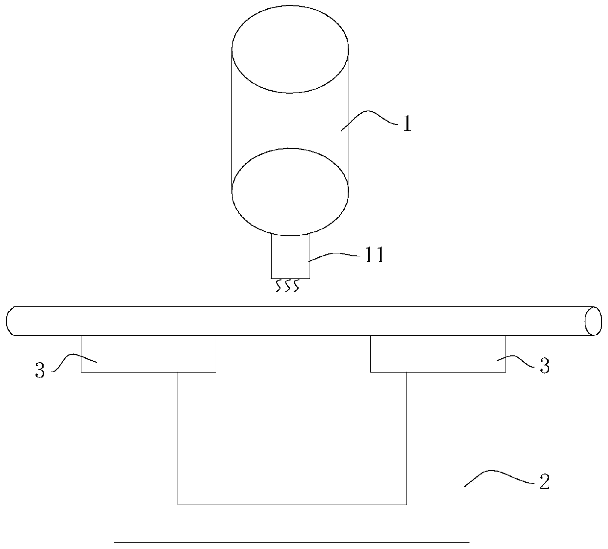
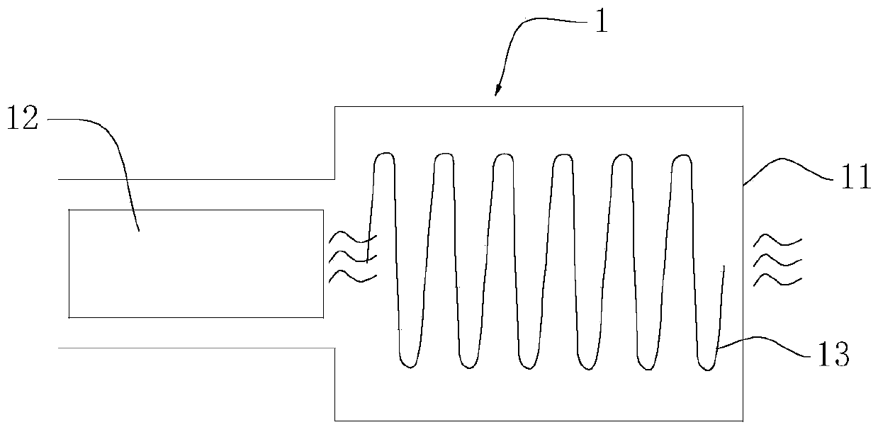
[0030] refer to figure 1 and figure 2 , the invention provides a kind of method for non-contact stripping optical fiber coating, comprises the following steps:

[0031] Place the optical fiber to be processed on the base 2, and fix the optical fiber to be processed by the optical fiber clamp 3;

[0032] Control the heating and air outlet of the heating device 1, and the hot air blown by the heating device 1 is maintained between 400°C and 600°C;

[0033] The control base 2 moves from the initial position to the bottom of the heating device 1, and the hot air blows vertically to the optical fiber to be processed;

[0034] Combined with the length interval of the optical fiber to be stripped, adaptively move the base 2 until the optical fiber coating layer of the optical fiber to be processed is stripped;

[0035] The control base 2 is moved back to the initial position, and the bare optical fiber that has been stripped of the optical fiber coating layer is removed.

[0036...


PUM


Abstract

The invention discloses a non-contact method for stripping an optical fiber coating layer. The non-contact method for stripping the optical fiber coating layer comprises the following steps: placing an optical fiber to be processed on a base, and fixing the optical fiber to be processed through an optical fiber clip; controlling the heating and air outflow of a heat generating device, and the hotair blown by the heat generating device is maintained between 400 degrees Celsius and 600 degrees Celsius; controlling the base to move to the lower side of the heat generating device from an initialposition, so that the hot air is blown vertically to the optical fiber to be processed; adaptively moving the base combining the length range to be stripped of the optical fiber to be processed untilthe stripping of the optical fiber coating layer of the optical fiber to be processed is completed; and controlling the base to move back to the initial position, and taking the bare optical fiber that the stripping of the optical fiber coating layer is completed. The non-contact method for stripping the optical fiber coating layer utilizes different ignition points of the optical fiber coating layer and the cladding layer to rapidly burn and decompose the optical fiber coating layer into carbon dioxide and water vapor, so as to complete the stripping and cleaning of the optical fiber coatinglayer in one time; and the non-contact method for stripping the optical fiber coating layer has the advantages of short time-consuming, high efficiency, no physical damage, convenient and quick.

Description

technical field [0001] The invention relates to the technical field of optical fibers, in particular to a non-contact method for stripping optical fiber coating layers. Background technique [0002] Explanation of terms: [0003] The core and cladding of the optical fiber: the central high-refractive index glass core (core diameter is generally 9, 50 or 62.5um) is called the core, which is used to transmit optical signals; the middle is a low-refractive index silica glass cladding (diameter is generally is 125um). [0004] Optical fiber coating: the outermost structure of the optical fiber (usually 250um in diameter). While the glass optical fiber is being drawn from the preform, a layer of elastomeric coating cured by UV light is applied to protect the cladding surface from contamination by dust. It is composed of acrylate, silicone rubber and nylon. [0005] In recent years, with the continuous progress of my country's national defense industry, aerospace, marine monit...

Claims


Application Information

Patent Timeline
IPC IPC(8): G02B6/245
CPCG02B6/245
Inventor 郭征东刘展武杜永建刘祖俊
Owner 广州奥鑫通讯设备有限公司
Why Eureka
Try Eureka