Multilayered electrode and film energy storage device

A multi-layer electrode and multi-layer structure technology, applied to battery electrodes, fixed capacitor electrodes, hybrid capacitor electrodes, etc., can solve the problems of increasing capacitors and increasing stored energy

Inactive Publication Date: 2019-08-30
CAPACITOR SCI
View PDF8 Cites 0 Cited by
  • Summary
  • Abstract
  • Description
  • Claims
  • Application Information

AI Technical Summary

Problems solved by technology

Increasing the voltage across the electrodes of a capacitor (such as a supercapacitor) results in an increase in stored energy

Method used


Image

  • Multilayered electrode and film energy storage device
  • Multilayered electrode and film energy storage device
  • Multilayered electrode and film energy storage device

Examples


Embodiment Construction

[0029] While various embodiments illustrating aspects of the disclosure have been shown and described herein, it will be obvious to those skilled in the art that such embodiments are provided by way of example only. Numerous variations, changes and substitutions may occur to those skilled in the art without departing from the invention. It should be understood that various alternatives to the embodiments of the invention described herein may be employed.

[0030] In this disclosure, the following terms are used.

[0031] The term "conductive layer" refers to a layer of conductive material formed, for example, by vacuum evaporation (deposition) of metal atoms or conductive organic molecules onto the surface of an arbitrary substrate. The outer surface of this layer may be roughened. The roughness of a surface can be thought of as a set of protrusions and cavities that form the microprofile of the surface. If such a conductive layer is used, for example, in a capacitor, high ...


PUM

PropertyMeasurementUnit
thicknessaaaaaaaaaa
breakdown field strengthaaaaaaaaaa
current densityaaaaaaaaaa

Abstract

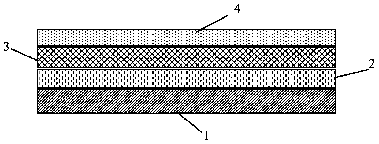
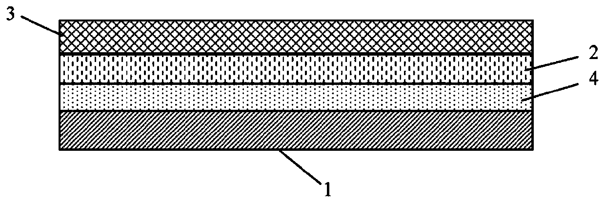
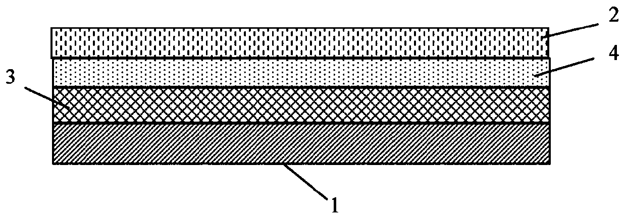
The present disclosure provides a multilayered electrode comprising an electro-conductive layer and at least one protective layer located on one side of the electro-conductive layer and selected fromthe list comprising a field-planarization layer, a tunneling injection blocking layer and a coulomb blocking layer.

Description

[0001] priority claim [0002] This application claims priority to US Patent Application Serial No. 15 / 368,171, filed December 2, 2017, the entire contents of which are incorporated herein by reference. technical field [0003] The present invention relates generally to passive components of electrical circuits, and more particularly to multilayer electrodes and membrane energy storage devices using the same. Background technique [0004] Electrode (contact) issues and fabrication methods for electrodes of electronic devices are widely discussed in the scientific and technical literature. [0005] The development of nanoscale MOSFETs has enabled the role of parasitic source / drain and contact resistance as performance limiting factors (see Reinaldo Vega and Tsu-Jae King Liu, "Advanced Source / Drain and Contact Design for Nanoscale CMOS", UC Berkeley Electrical Engineering and Computer Science, Technical Report No. UCB / EECS-2010-84, http: / / www.eecs.berkeley.edu / Pubs / TechRpts / ...

Claims


Application Information

Patent Timeline
Patent Type & Authority Applications(China)
IPC IPC(8): H01M4/60H01G11/48H01L27/28H01L29/43
CPCH01B1/127C08G2261/3142C08G2261/3221C08G2261/3223C08G2261/3241C08G2261/3422C08G2261/51H01B1/128C08G73/0266C08G73/0672H01G4/32H01G4/33H01G4/14H01G4/008H01G4/01C09D5/24C09D165/00
Inventor 帕维尔·拉扎列夫保罗·富鲁塔贝里·夏普李炎
Owner CAPACITOR SCI
Why Eureka
Try Eureka