Flue gas waste heat recovery system and method for air pollution control

A flue gas waste heat and recovery system technology, applied in the field of flue gas waste heat recovery, can solve the problems such as the inability to automatically adjust the cold water flow rate of the recovery system, the inability to effectively remove particulate pollutants, and the large volume of the flue gas waste heat recovery system. Compact structure, labor saving, and the effect of improving the heat recovery rate

Inactive Publication Date: 2019-09-06
JILIN JIANZHU UNIVERSITY
View PDF5 Cites 1 Cited by
  • Summary
  • Abstract
  • Description
  • Claims
  • Application Information

AI Technical Summary

Problems solved by technology

[0003] 1. The existing flue gas waste heat recovery system for air pollution control cannot effectively remove the particulate pollutants in the flue gas during the process of recovering the heat of the flue gas
[0004] 2. The existing flue gas waste heat recovery system for air pollution control is bulky, resulting in increased costs
[0005] 3. During the flue gas waste heat recovery process, the existing flue gas waste heat recovery system for air pollution control cannot automatically adjust the cold water flow rate of the entire recovery system according to the detected data, which may easily lead to waste heat recovery.
[0007] (1) The existing flue gas waste heat recovery system for air pollution control cannot effectively remove the particulate pollutants in the flue gas during the process of recovering the heat of the flue gas
[0008] (2) The existing flue gas waste heat recovery system for air pollution control is bulky, resulting in increased costs
[0009] (3) During the flue gas waste heat recovery process, the existing flue gas waste heat recovery system for air pollution control cannot automatically adjust the cold water flow rate of the entire recovery system according to the detected data, which may easily lead to a high waste heat recovery rate.

Method used


Image

  • Flue gas waste heat recovery system and method for air pollution control
  • Flue gas waste heat recovery system and method for air pollution control
  • Flue gas waste heat recovery system and method for air pollution control

Examples


Embodiment Construction

[0048] In order to further understand the invention content, characteristics and effects of the present invention, the following embodiments are listed below, and detailed descriptions are as follows in conjunction with the accompanying drawings.

[0049] The structure of the present invention will be described in detail below in conjunction with the accompanying drawings.

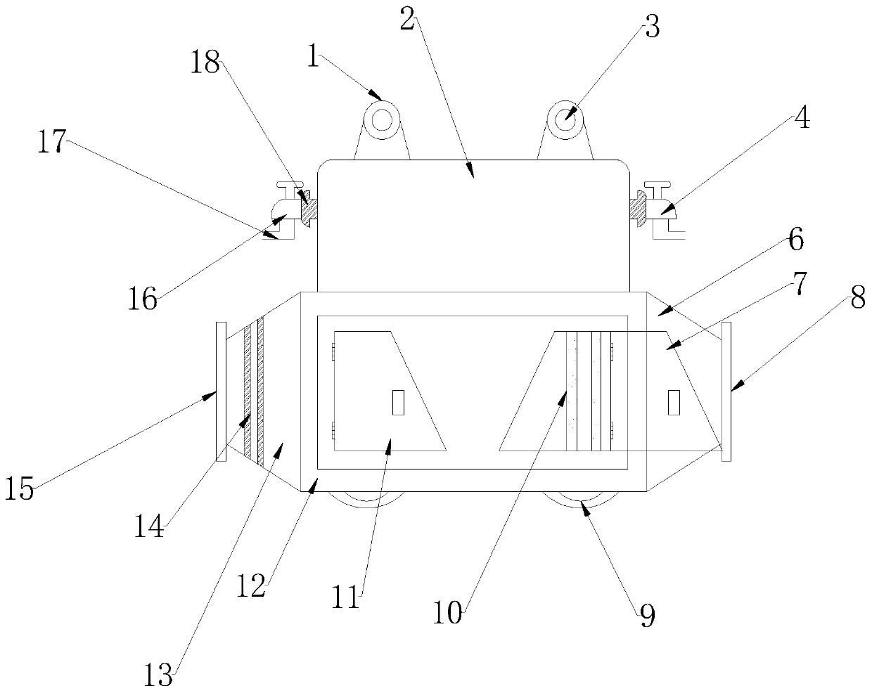
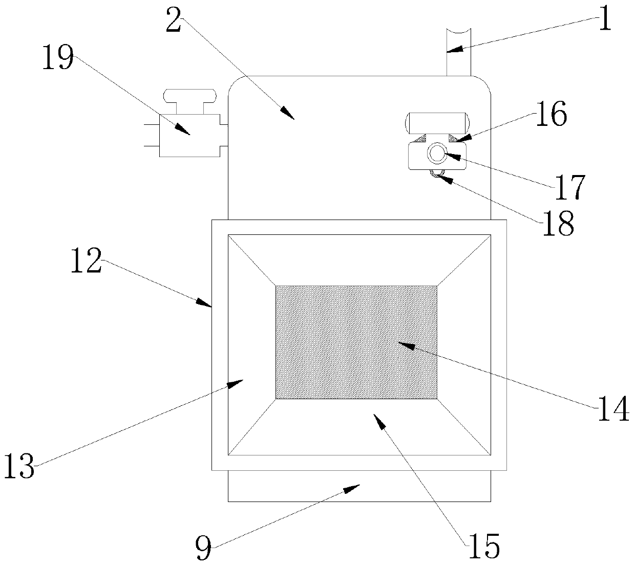
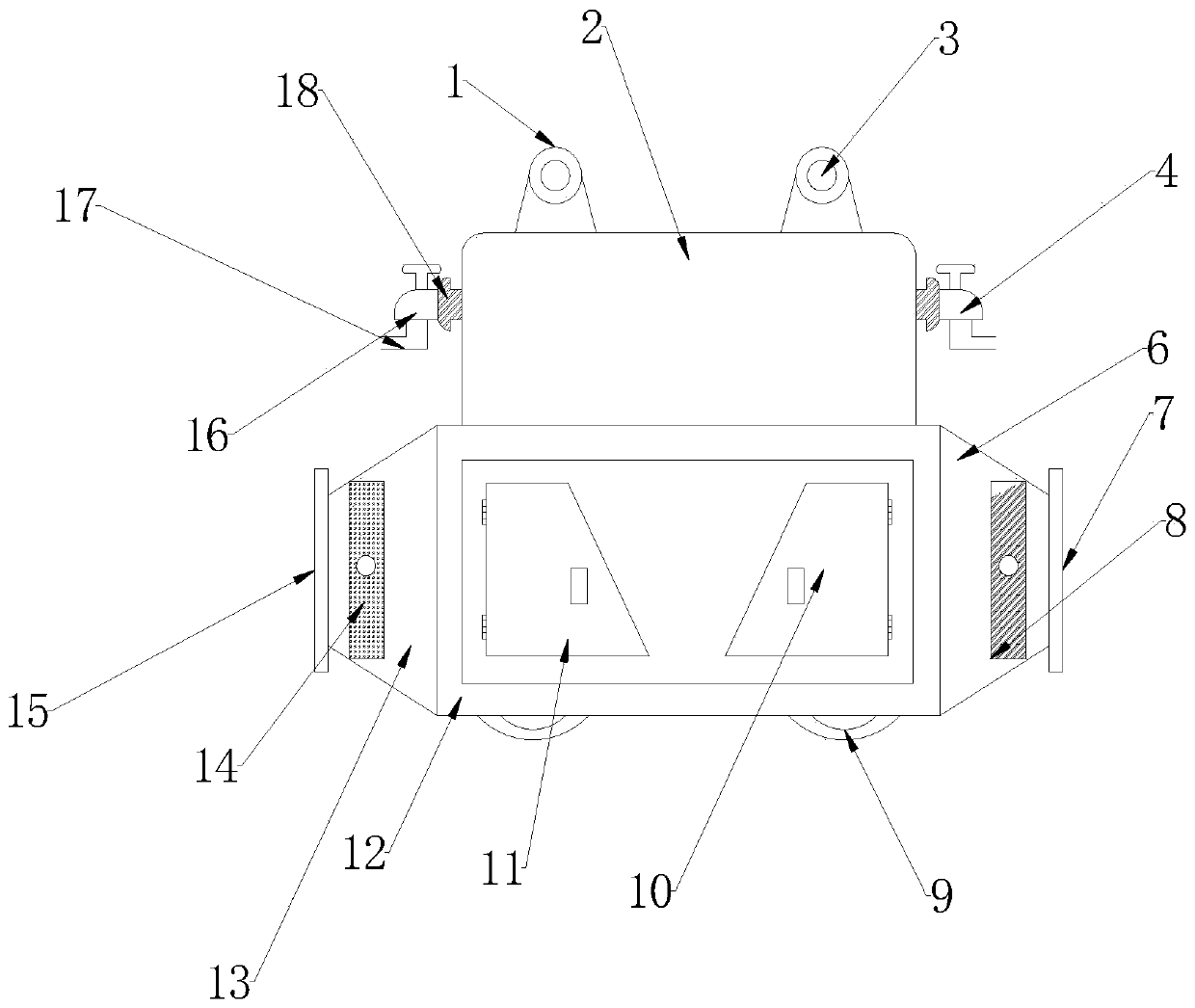
[0050] like Figure 1-Figure 3As shown, the flue gas waste heat recovery device for air pollution control is equipped with a pressure gauge 1, a water tank 2, a thermometer 3, a drain valve 4, a drain pipe 5, a smoke exhaust end cover 6, an activated carbon filter 7, a smoke exhaust port 8, and a base 9. Heat pipe 10, box door 11, cabinet body 12, smoke inlet cover 13, filter cotton layer 14, smoke inlet 15, water inlet valve 16, water inlet pipe 17, pipe ring 18, sewage valve 19.

[0051] The main structure of the flue gas waste heat recovery device for air pollution control is a cabinet body 12, and the...


PUM


Abstract

The invention belongs to the technical field of flue gas waste heat recovery, and discloses a flue gas waste heat recovery system and method for air pollution control. A water tank is installed at thetop of a case body, and a pressure gauge and a temperature gauge are arranged at the two sides of the water tank respectively and used for monitoring the change conditions of the pressure and temperature in the water tank in real time; meanwhile, a water inlet valve and a water outlet valve are installed at the outer portion of the water tank, and the water inlet valve is connected with a water inlet pipe. The water inlet valve and the water outlet valve are connected with the water tank through pipeline through rings. An activated carbon filtering net layer and a drawer-type filtering surface layer are laid in a filtering device in the case body and can effectively adsorb small solid particles or sulfur dioxide and other gas in waste flue gas and improve the working efficiency. The pipeline through rings between the water inlet valve and the water outlet valve can activate water molecules, prevent the formation of scales and reduce the water corrosion to pipelines. Two symmetrical bases are installed at the bottom of the case body to achieve a symmetric effect.

Description

technical field [0001] The invention belongs to the technical field of flue gas waste heat recovery, and in particular relates to a flue gas waste heat recovery system and method for air pollution control. Background technique [0002] Smoke is very common in industrial production, and is often the most exhaust gas in the production of many heavy industrial machinery. Especially in some industries with high energy consumption and serious pollution. The random discharge of waste flue gas containing a large amount of heat into the air will not only cause energy loss, but also pollute the air environment to a certain extent, posing a great threat to people's health. And if this part of waste flue gas can be recovered and the heat carried by it can be converted into other energy, it will not only reduce the pollution to the environment but also improve the efficiency of energy utilization. However, at present, no matter whether it is industrial treatment or market production, ...

Claims


Application Information

Patent Timeline
Patent Type & Authority Applications(China)
IPC IPC(8): B01D46/10B01D53/78B01D53/40F23J15/06F28D7/00F28F27/00F28G7/00G01D21/02G05D27/02
CPCB01D46/10B01D53/04B01D53/40B01D53/78B01D2258/0283F23J15/06F28D7/00F28F27/00F28G7/00G01D21/02G05D27/02Y02E20/30Y02A50/2351
Inventor 孙雪景
Owner JILIN JIANZHU UNIVERSITY
Why Eureka
Try Eureka