Water-distribution, gas-distribution and aeration multifunctional filter tube, multifunctional filter tube filter tank, and water treatment method

A multi-functional, filter tube technology, applied in the field of water treatment, can solve the problems that the quantity and quality of aeration bubbles are difficult to guarantee, the structure of the water distribution and air distribution aeration system is complicated, and the aeration volume is difficult to control precisely, and the aeration volume can be achieved. Balanced and consistent, easy and fast installation, independent function effect

Pending Publication Date: 2019-09-06
惠州市铭博实业发展有限公司
View PDF0 Cites 2 Cited by
  • Summary
  • Abstract
  • Description
  • Claims
  • Application Information

AI Technical Summary

Problems solved by technology

[0005] The purpose of the present invention is to provide a multifunctional filter tube for water distribution, air distribution and aeration, a multifunctional filter tube filter tank and a water treatment method, to solve the technical problem that the generation quantity and quality of aeration bubbles are difficult to guarantee; and to solve the aeration rate Difficult to precisely control the problem, and solve the problem of complex structure and low efficiency of the biological aerated filter water distribution and air distribution aeration system

Method used


Image

  • Water-distribution, gas-distribution and aeration multifunctional filter tube, multifunctional filter tube filter tank, and water treatment method
  • Water-distribution, gas-distribution and aeration multifunctional filter tube, multifunctional filter tube filter tank, and water treatment method
  • Water-distribution, gas-distribution and aeration multifunctional filter tube, multifunctional filter tube filter tank, and water treatment method

Examples


Embodiment Construction

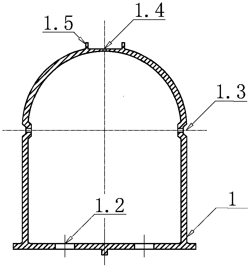
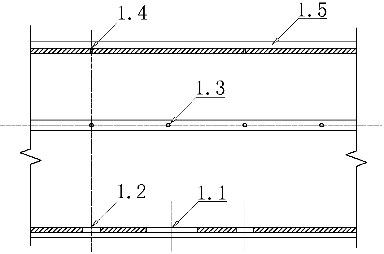
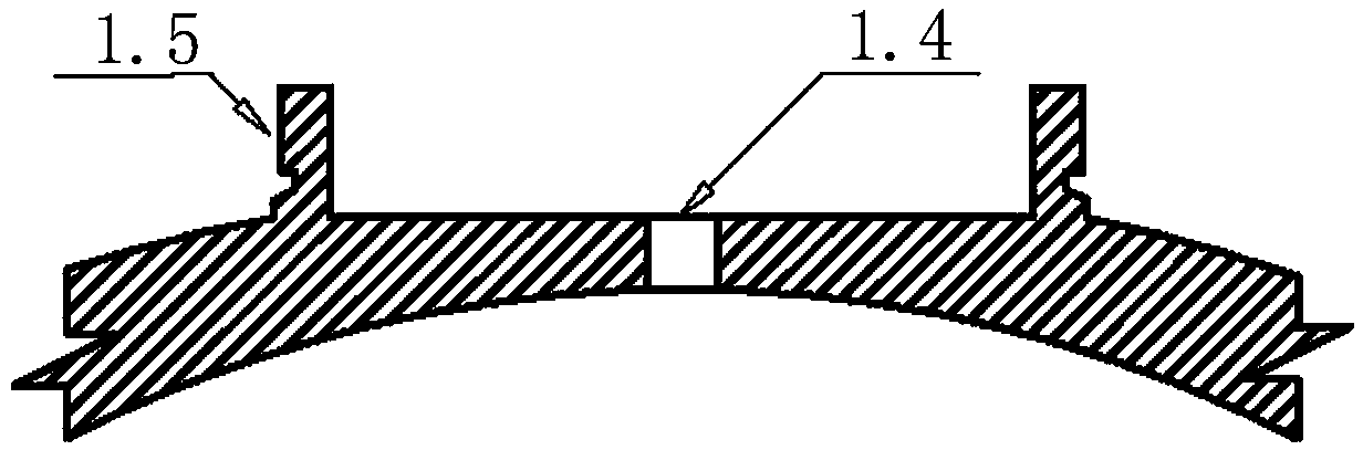
[0048] Examples see Figure 1A , 1B As shown, a multifunctional filter tube for water distribution, gas distribution and aeration, the filter tube 1 is a strip tubular structure, and its cross section is arched; the top of the filter tube 1 is distributed with air distribution holes 1.4 on the top of the filter tube, two The side waist is correspondingly provided with a groove, and the air distribution holes 1.3 on both sides of the filter tube are arranged at the bottom of the groove; the filter pipe water distribution holes 1.2 have two rows, which are symmetrically arranged on both sides of the long axis of the filter tube bottom plate, and the bottom plate is also provided with A vertical pipe insertion hole 1.1; the water distribution holes 1.2 of the filter pipe, the air distribution holes 1.3 on both sides of the filter pipe and the air distribution holes 1.4 on the top of the filter pipe are evenly spaced along the length of the filter pipe 1.

[0049] see figure 2 A...


PUM


Abstract

The invention relates to a water-distribution, gas-distribution and aeration multifunctional filter tube, a multifunctional filter tube filter tank, and a water treatment method. The filter tube has astrip-shaped tubular structure and an arched cross section, the top of the filter tube is provided with a filter tube top gas distribution hole, two sides of the waist part of the filter tube are symmetrically provided with filter tube side gas distribution holes, and the bottom plate of the filter tube is provided with filter tube water distribution holes and a vertical tube insertion hole; anda position, corresponding to the filter tube top gas distribution hole, of the top outer wall of the filter tube is detachably connected with an aerator. The filter tube of the invention has strong versatility, can be used in a conventional filter tank not requiring aeration, and also can be used in a filter tank that requires aeration. The filter tube of the invention can be widely applied to various types of new filter tanks such as a V-shaped filter tank, a deep bed filter tank and a flap filter tank, and can also be used in various filter tank reconstruction projects to achieve the purposeof replacing two independent water treatment process systems, required for the aeration process, the water distribution process and the gas distribution process in a biological aerated filter tank, with one process system.

Description

technical field [0001] The invention relates to the field of water treatment, in particular to a water treatment device component and a water treatment method. Background technique [0002] The biological aerated filter realizes the oxidative degradation of organic matter through the aeration function in the water treatment process. This process can not only effectively remove some fine suspended particles and colloidal substances that cannot be removed by coagulation and sedimentation, but also efficiently remove COD, BOD, Harmful substances in water such as phosphorus, heavy metals, bacteria and viruses. Therefore, it is an indispensable process unit in tap water production pretreatment and sewage treatment engineering. [0003] In order to realize the water filtration, backwashing and aeration process, the traditional biological aerated filter uses a set of water distribution and gas distribution system for water filtration and backwashing operation plus an aeration syst...

Claims


Application Information

Patent Timeline
Patent Type & Authority Applications(China)
IPC IPC(8): C02F9/14
CPCC02F1/001C02F3/02C02F7/00C02F2303/14
Inventor 汪平颜述敏杜凌楠颜锦波
Owner 惠州市铭博实业发展有限公司
Why Eureka
Try Eureka