A multifunctional cutting machine

A cutting machine, multi-functional technology, applied in the cutting of textile materials, fabric surface trimming, textiles and papermaking, etc., can solve the problems of heavy workload, inaccurate cutting of manual line drawing, etc., to improve production efficiency, reduce deformation, The effect of avoiding traces

Active Publication Date: 2020-11-24
湖南省逸谭工贸有限公司
View PDF6 Cites 0 Cited by
  • Summary
  • Abstract
  • Description
  • Claims
  • Application Information

AI Technical Summary

Problems solved by technology

[0006] The embodiment of the present application provides a multi-functional cutting machine to solve the inaccurate and heavy workload of manual line drawing and cutting proposed in the above-mentioned background technology, and at the same time avoid the curling of the cutting mouth after cutting to the greatest extent, and can reduce the operation cost. The workload of personnel and the problem of improving production efficiency

Method used


Image

  • A multifunctional cutting machine
  • A multifunctional cutting machine
  • A multifunctional cutting machine

Examples


Embodiment 1

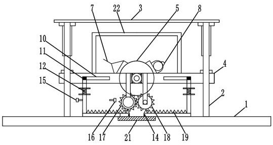
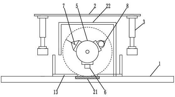
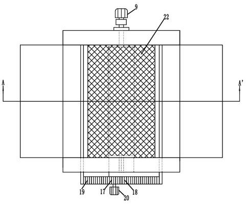
[0026] Such as Figure 1-3 As shown, a multifunctional cutting machine includes a workbench 1, a support frame 2 is fixed on the workbench 1, and a hydraulic rod 3 is fixed upside down on the bottom surface of the top of the support frame 2, and the hydraulic rod 3 is connected with a hydraulic pump station, There is an operation button for controlling the expansion and contraction of the hydraulic rod 3; a set of beams 4 are connected under the hydraulic rod 3, and the beam 4 is provided with a bearing seat in the middle position. The shaft at one end of the drum 5 is connected to the bearing seat, and the shaft at the other end of the drum 5 penetrates The bearing seat on the beam 4 is connected to the first stepping motor 9 through a coupling. The first stepping motor 9 provides power for the rotation of the drum 5; the surface of the drum 5 is provided with a laser marking device 6 at the center position. The preferred model of the marking device 6 is LTA200L-30. The length...

Embodiment 2

[0028] The working method of a multifunctional cutting machine is as follows: When the cloth needs to be cut, the operator fully unfolds the cloth on the worktable 1 and keeps it flat, the drum 5 is in the initial position, and the laser marker 6 is at the bottom, and the laser is turned on The switch of the marking device 6, the marking line of the laser marking device 6 is projected on the cloth, the operator can adjust the cloth according to the cutting size, and after the adjustment is correct, the first stepping motor 9 is started, and the first stepping motor 9 drives the drum 5 to rotate After the drum 5 rotates 120°, the cutter 7 moves to the lowermost position and is tangent to the reinforcement block 21 on the worktable 1 to complete the cutting of the cloth; the drum 5 continues to rotate until the atomizing nozzle 8 reaches the bottom, and then the control The controller stops the rotation of the first stepping motor 9 and starts the water pump at the same time. The ...


PUM


Abstract

The invention discloses a multifunctional cutting machine, which comprises a workbench and a supporting frame. A group of hydraulic rods and a crossbeam are arranged on the supporting frame, a rolleris arranged on the crossbeam and provided with a laser line marker for cloth marking alignment, a cutter arranged on the roller is used for cloth cutting, an atomizing nozzle arranged on the roller isused for wetting cloth cuts, and heating plates are arranged under the roller and capable of heating and ironing the wetted cloth cuts to eliminate curls at the cuts. By arrangement of the laser linemarker, the cutter and the atomizing nozzle on the same roller, line marking, cutting and wetting of cloth can be completed in one time under the control of a controller, then the controller controlsa step motor to drive a group of meshed gears to enable relative movement of the heating plates to cover the cloth cuts and heat and iron the wetted cloth cuts, and accordingly the curls can be eliminated. The multifunctional cutting machine is high in automation degree, workload of operating personnel is sharply relieved, and operating efficiency is improved.

Description

Technical field [0001] The invention relates to the field of textile devices, in particular to a multifunctional cutting machine. Background technique [0002] The cutting machine is one of the indispensable tools for fabric processing. When the processed fabric needs to be cut according to the specified size, follow the general cutting process. When cutting, first draw a line manually, and then use scissors to cut along the line, or Put the line-drawing fabric on the worktable with a ruler, and align the line-drawing with the ruler and cut it with a cutting machine. The above cutting method has at least the following problems: [0003] 1. The operator needs to use a ruler, tape measure and other tools to draw a line on the place to be cut. If the operation is not accurate, the cutting line will be drawn obliquely and the fabric will be cut obliquely, affecting the use of the fabric, especially for some expensive fabrics When using the workbench to cut, you can only use the scales...

Claims


Application Information

Patent Timeline
Patent Type & Authority Patents(China)
IPC IPC(8): D06H7/00D06H1/00D06C15/10D06B1/02
CPCD06B1/02D06C15/10D06H1/00D06H7/00
Inventor 张华艳
Owner 湖南省逸谭工贸有限公司
Why Eureka
Try Eureka