Optical conversion multi-beam conformal lens antenna

A technology of optical transformation and lens antenna, which is applied to antennas, antenna arrays, antenna grounding devices, etc. to achieve the effect of improving gain

Inactive Publication Date: 2019-09-06
XIDIAN UNIV
View PDF5 Cites 7 Cited by
  • Summary
  • Abstract
  • Description
  • Claims
  • Application Information

AI Technical Summary

Problems solved by technology

In practice, this is due to the fact that a different spatial phase difference is introduced between adjacent elements in a c

Method used


Image

  • Optical conversion multi-beam conformal lens antenna
  • Optical conversion multi-beam conformal lens antenna
  • Optical conversion multi-beam conformal lens antenna

Examples


example

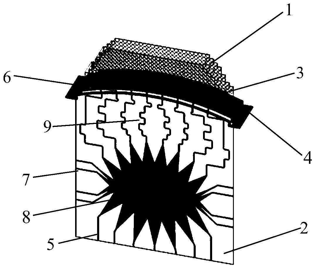
[0035] The dielectric lens is made of a dielectric block with a dielectric constant of 2.2, and the overall size is 360×107.3×50mm 3 , the unit block size is 10×10mm 2 .

[0036] The patch unit is composed of a dielectric block with a dielectric constant of 2.2, a dielectric plate with a dielectric constant of 2.65, and a copper clad surface. The thicknesses of the two dielectric blocks with a dielectric constant of 2.2 are 8.5mm and 7mm respectively, and the dielectric constant is 2.65. The thickness of the two dielectric boards is 1mm, and the size of the dielectric board is 60×39.6mm 2 , There are through holes with a radius of 1mm around each layer of the board, and the two layers of dielectric boards are covered with good conductive metal materials, such as aluminum or copper.

[0037] The conformal floor is made of good conductive metal material, its thickness is 4mm, and the overall size is 435.3mm×100mm. There are 7mm wide and 400mm long slots on the conformal floor...


PUM

PropertyMeasurementUnit
Thicknessaaaaaaaaaa

Abstract

The invention relates to an optical conversion multi-beam conformal lens antenna. The optical conversion multi-beam conformal lens antenna comprises four parts comprising a dielectric lens, a multi-beam Rotman lens, a cylindrical conformal microstrip antenna array and a conformal floor, wherein the dielectric lens covers the cylindrical conformal microstrip antenna array, the conformal microstripantenna array is placed on the conformal floor, and the multi-beam Rotman lens is used for feeding the cylindrical conformal microstrip antenna array. By covering the cylindrical conformal array withthe quasi-conformal optical conversion dielectric lens, the cylindrical conformal array is equivalent to a virtual space planar array, and the converted non-uniform dielectric constant distribution isachieved by a dielectric punching periodic structure; the multi-beam Rotman lens is a multi-beam feeding network of the antenna and comprises a dielectric substrate, a copper laying plane, an input port, an output port, a virtual port, a copper laying lens cavity and a transmission line, the copper laying plane is formed on a lower surface of the substrate, the copper laying lens cavity is formedin an upper surface of the substrate, and the transmission line is connected with the lens and the conformal array; and by the optical conversion multi-beam conformal lens, seven beams within a coverage range being (-45)-(+45) degrees can be formed.

Description

technical field [0001] The invention belongs to the field of integrated multi-beam technology and the field of antenna technology, in particular to a multi-beam conformal lens antenna based on an optical conversion method. Background technique [0002] In modern radar and communication systems, antennas are often required to have beam scanning function and multi-beam characteristics. Multi-beam technology can greatly improve the coverage radiation power and channel capacity, so as to maximize the use of spectrum resources, which makes it widely used in navigation, communication, detection and other fields. [0003] The multi-beam antenna mainly includes three parts: beamforming network, phase shifter and antenna array. Among them, the beamforming network can be divided into two types: matrix type and lens type. The typical matrix-like beamforming network is the Butler matrix, which is not widely used due to its large size, complex structure, and high processing cost. A ty...

Claims


Application Information

Patent Timeline
IPC IPC(8): H01Q19/06H01Q15/08H01Q15/02H01Q21/20H01Q21/29H01Q21/00H01Q1/38H01Q1/48H01Q1/50
CPCH01Q1/38H01Q1/48H01Q1/50H01Q15/02H01Q15/08H01Q19/06H01Q21/0031H01Q21/20H01Q21/293
Inventor 雷娟杨万年傅光
Owner XIDIAN UNIV
Why Eureka
Try Eureka