
Three-phase unbalance and reactive power control automatic switching device and method

An automatic switching and three-phase technology, which is applied in reactive power compensation, circuit devices, multi-phase network asymmetry reduction, etc., can solve the problems of reducing the power factor of the power supply system, burning of distribution transformers, and voltage drop, etc., to achieve improved The effects of practicality and accuracy, fast response and high compensation accuracy

Active Publication Date: 2019-09-06
ZHEJIANG UNIV OF TECH
View PDF3 Cites 3 Cited by
  • Summary
  • Abstract
  • Description
  • Claims
  • Application Information

AI Technical Summary

Problems solved by technology

During the operation of these devices, not only must consume a certain amount of active power, but also consume a large amount of reactive power.
When a large amount of reactive power enters the electrical equipment through the transmission and distribution system, it will reduce the power factor of the power supply system, cause line loss, and cause a voltage drop. At the same time, the electrical equipment is frequently connected or In the case of withdrawal, the low-voltage three-phase unbalance phenomenon occurs from time to time, which can reduce the power supply efficiency of lines and distribution transformers, and cause serious consequences such as wire burnout, switch burnout, and even distribution transformer burnout.
However, for a long time, the low-voltage system has almost no effective means to make reasonable adjustments except to distribute the load as reasonably as possible.

Method used


Image

  • Three-phase unbalance and reactive power control automatic switching device and method
  • Three-phase unbalance and reactive power control automatic switching device and method
  • Three-phase unbalance and reactive power control automatic switching device and method

Examples


Embodiment Construction

[0037] The present invention will be further described below in conjunction with the accompanying drawings.

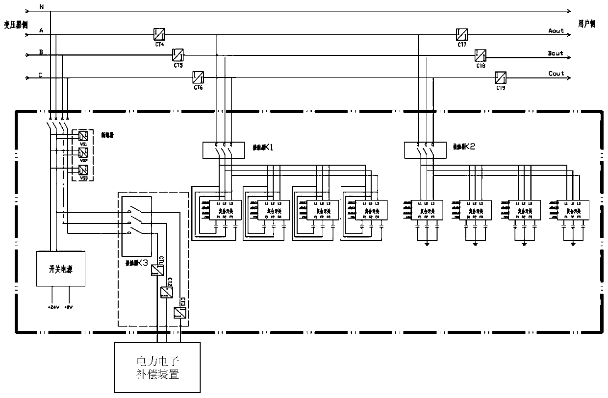
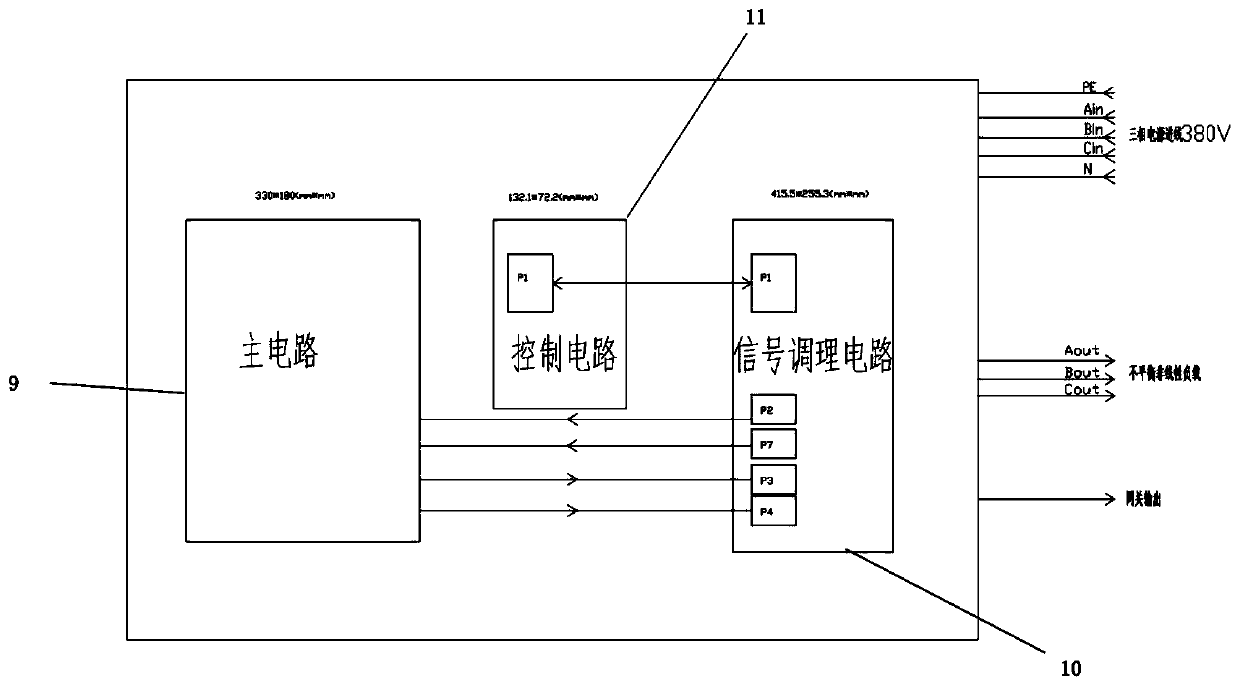
[0038] refer to figure 1 with figure 2 , an automatic switching device for three-phase unbalance and reactive power management, comprising a control circuit 11, a signal conditioning circuit 10 connected to the control circuit, a main circuit 9 connected to the signal conditioning circuit, the main circuit comprising a switching power supply 6, Voltage acquisition device 8, current acquisition device 1, contactor 2, circuit breaker 5, smart capacitor bank 34 and power electronic compensation device 7; said smart capacitor bank includes phase-to-phase compensation capacitor 3 and phase-to-ground compensation capacitor 4, phase-to-phase compensation capacitor 3 It includes multiple groups of capacitance adjustment branches 3-1 connected between the three phases, and the phase-ground compensation capacitor 4 includes multiple groups of capacitance adjustment branches 4-...


PUM


Abstract

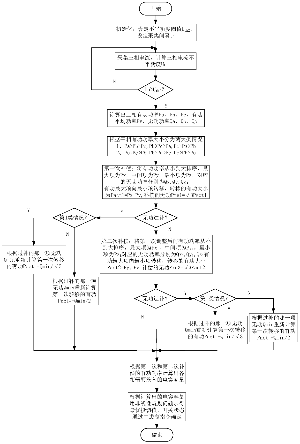
The invention provides a three-phase unbalance and reactive power control automatic switching device. The main circuit comprises a switching power supply, a voltage acquisition device, a current acquisition device, a contactor, a circuit breaker, an intelligent capacitor bank and a power electronic device. The intelligent capacitor bank comprises a phase-to-phase compensation capacitor and a phase-to-ground compensation capacitor and comprises multiple sets of capacitance adjusting branches which are connected among the three phases and between the phase and the ground. A composite switch is connected on each branch. The contactor is connected between the intelligent capacitor bank and a bus. The data collected by the current acquisition device and the voltage acquisition device are transmitted to the controller of the main circuit, and the active power and the reactive power of each item are calculated inside the controller and the capacities of the phase-to-phase capacitor bank, thephase-to-ground capacitor bank and the power electronic compensation device which are required to be switched on and off are calculated according to the power magnitude. The accuracy is high and the response speed is fast so that the station area of the distribution network with serious three-phase load imbalance problem can be dynamically controlled and the operation state of the transformer in the station area can be monitored.

Description

technical field [0001] The invention relates to an automatic switching device and method for three-phase unbalance control of a low-voltage distribution network, and belongs to the technical field of power quality control. Background technique [0002] In the power system, due to the existence of inductance and capacitance, there is not only active power but also reactive power in the system. With the development of modern industry and power electronics technology, a large number of equipment with low power factor, nonlinearity, asymmetry and other characteristics are used in the low-voltage distribution network, such as motors, electric welding machines, thyristors, etc. During the operation of these devices, not only must consume a certain amount of active power, but also consume a large amount of reactive power. When a large amount of reactive power enters the electrical equipment through the transmission and distribution system, it will reduce the power factor of the po...

Claims


Application Information

Patent Timeline
IPC IPC(8): H02J3/26H02J3/18
CPCH02J3/1864H02J3/26Y02E40/30Y02E40/50
Inventor 张有兵余金城谢路耀叶森徐向志
Owner ZHEJIANG UNIV OF TECH
Learn More