Ultrahigh-voltage phase modifier system applied to extra-high voltage converter station
An ultra-high voltage, camera-modulating technology, applied in electromechanical devices, AC network circuits, reactive power adjustment/elimination/compensation, etc., can solve the problem of affecting economic benefits, increasing costs, and increasing the space requirements of large-scale camera-modulating systems, etc. problems, to achieve the effect of improving overall reliability, reducing copper consumption, and improving dynamic reactive power output capability
- Summary
- Abstract
- Description
- Claims
- Application Information
AI Technical Summary
Problems solved by technology
Method used
Image
Examples
Embodiment 1
[0035] The invention is applied to an ultra-high voltage direct current converter station, and its function is to provide dynamic and steady-state reactive power support and reactive power compensation.
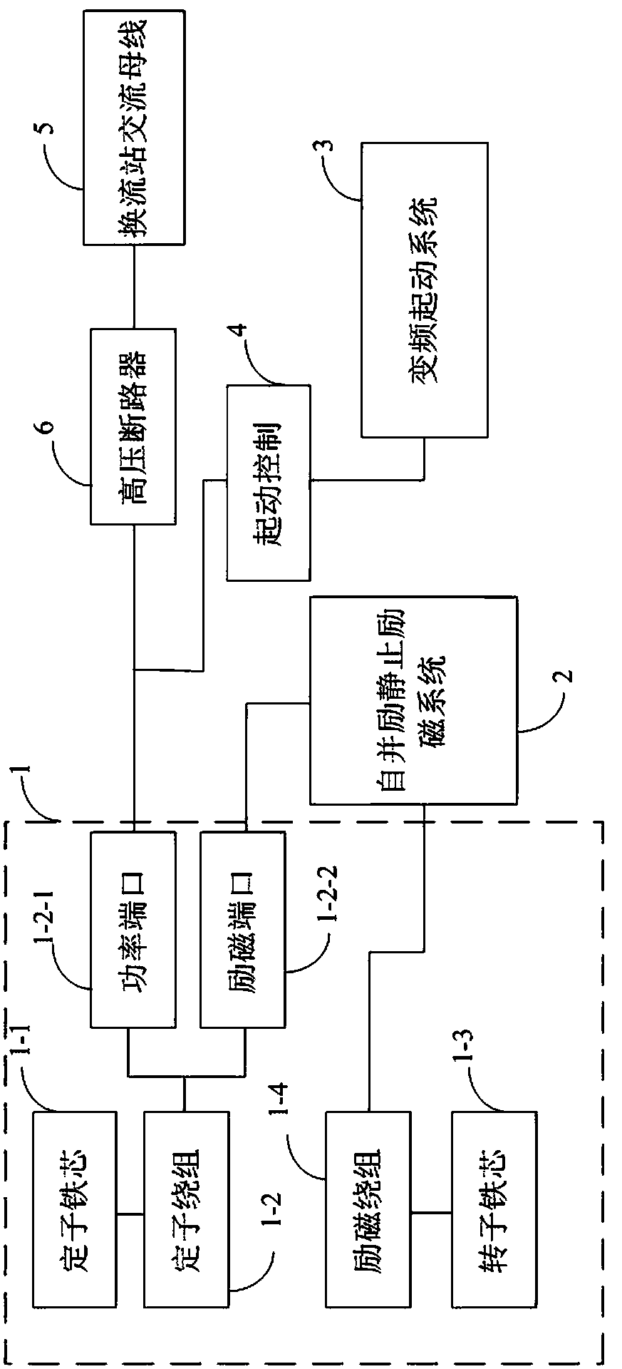
[0036] This embodiment provides an ultra-high voltage condenser system. figure 1 It shows the functional block diagram of the ultra-high voltage condenser system provided by the embodiment of the present invention, and the details are as follows:
[0037] The ultra-high voltage condenser system includes an ultra-high voltage condenser 1, a self-shunt excitation static excitation system 2, a variable frequency starting system 3, a starting control module 4, an AC bus 5 of an ultra-high voltage converter station, and a high-voltage circuit breaker 6 at the outlet end; among them, Ultra-high voltage condenser 1 includes: stator core 1-1 and three-phase stator winding 1-2, rotor core 1-3, rotor excitation winding 1-4, output ports of three-phase stator winding 1-2 include excitat...
Embodiment 2
[0047] As another preferred embodiment of the present invention, this embodiment discloses:
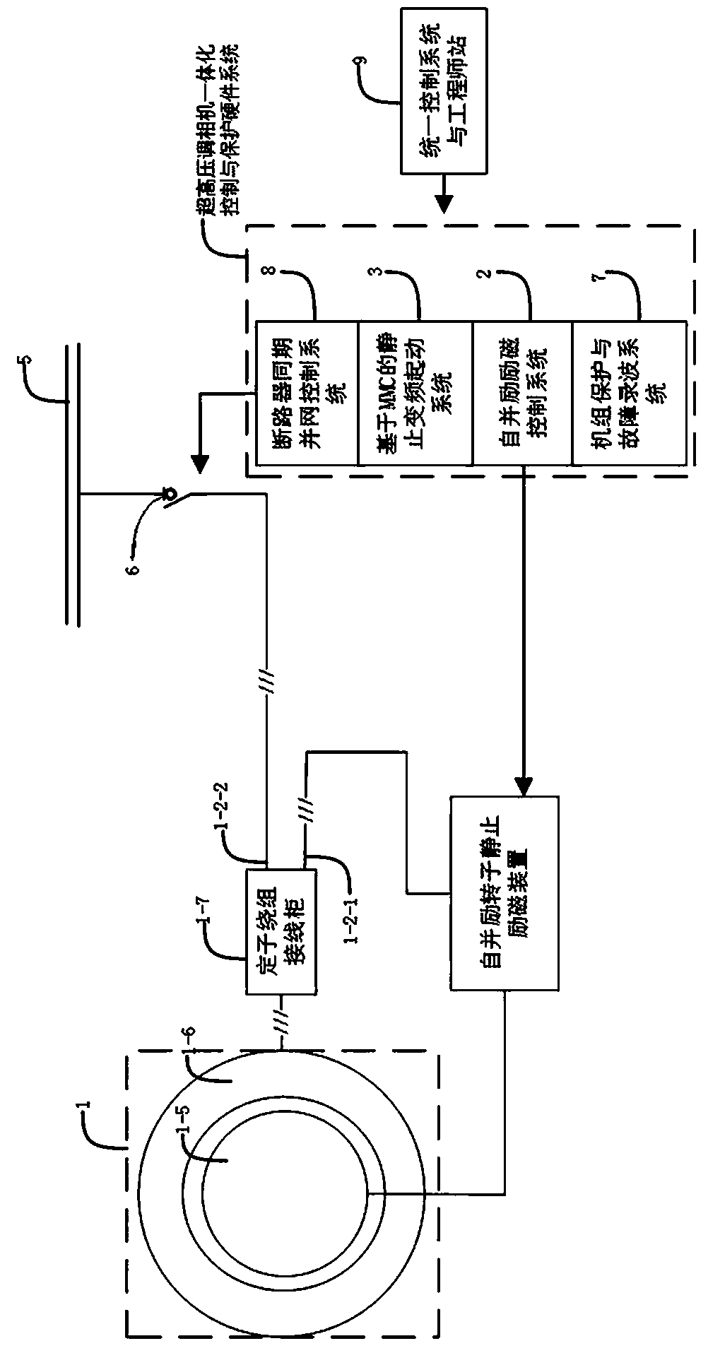
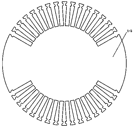
[0048] An ultra-high voltage condenser system applied in an ultra-high voltage converter station, including an ultra-high voltage condenser 1, a self-shunt excitation static excitation system 2, and a variable frequency starting system 3; the ultra-high voltage condenser includes a stator 1-6 and a rotor 1-5, the stator 1-6 is composed of a stator core 1-1 and a stator winding 1-2, the rotor 1-5 includes a rotor core 1-3 and a rotor field winding 1-4, and the stator winding 1-2 It is made of cross-linked polyethylene cables to form a symmetrical Y-connected three-phase stator winding. By using cross-linked polyethylene cables instead of traditional forming wire rods to manufacture stator windings, the stator winding terminal voltage of large-scale condensers can be designed. In order to be equivalent to the voltage of the AC busbar of the converter station, it is possible to directly ...
Embodiment 3
[0051] As another preferred embodiment of the present application, refer to the attached figure 1 and 2 , this example discloses:
[0052] An ultra-high voltage condenser system applied in an ultra-high voltage converter station, including an ultra-high voltage condenser 1, a self-shunt excitation static excitation system 2, and a variable frequency starting system 3; the ultra-high voltage condenser 1 includes stators 1-6 and The rotor 1-5, the stator 1-6 consists of a stator core 1-1 and a stator winding 1-2, the rotor 1-5 includes a rotor core 1-3 and a rotor field winding 1-4, the stator Winding 1-2 is made of cross-linked polyethylene cables to form a symmetrical Y-connected three-phase stator winding. In the stator winding 1-2, 2M taps are extracted from each phase winding at equal and symmetrical positions to form M strips The branch circuit, the non-neutral point tap of the branch circuit closest to the neutral point 1-12 is used as the excitation port 1-2-1, and the...
PUM
 Abstract
Description
Claims
Application Information
 - R&D
- Intellectual Property
- Life Sciences
- Materials
- Tech Scout
- Unparalleled Data Quality
- Higher Quality Content
- 60% Fewer Hallucinations
Browse by: Latest US Patents, China's latest patents, Technical Efficacy Thesaurus, Application Domain, Technology Topic, Popular Technical Reports.
© 2025 PatSnap. All rights reserved.Legal|Privacy policy|Modern Slavery Act Transparency Statement|Sitemap|About US| Contact US: help@patsnap.com


