
Microwave amplifier and implementation method thereof

A technology of microwave amplifiers and circulators, which is applied in the direction of amplifiers, amplifier input/output impedance improvements, improved amplifiers to reduce noise effects, etc., to achieve the effects of simple structure, good flexibility, and low operating temperature requirements

Active Publication Date: 2019-09-06
UNIV OF ELECTRONICS SCI & TECH OF CHINA
View PDF12 Cites 2 Cited by
  • Summary
  • Abstract
  • Description
  • Claims
  • Application Information

AI Technical Summary

Problems solved by technology

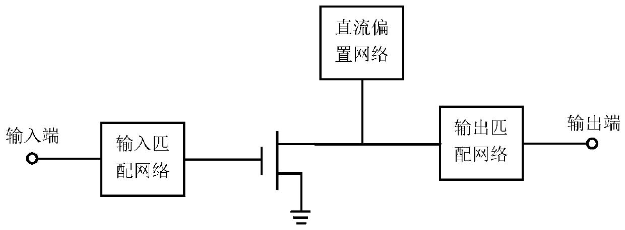
[0003] In order to solve the crosstalk existing in the existing DC bias amplifier and the low-noise amplifier’s dependence on the low-temperature environment, the present invention proposes a microwave amplifier and its realization method. When the element is excited to a high energy level, the chain effect of the input signal in the energy level transition process is used to make the polaritons excited to the high energy level jump down to the specified energy level in the energy level region, and the power of the input signal is amplified.

Method used


Image

  • Microwave amplifier and implementation method thereof
  • Microwave amplifier and implementation method thereof
  • Microwave amplifier and implementation method thereof

Examples


Embodiment Construction

[0022] In order to facilitate those skilled in the art to understand the technical content of the present invention, the content of the present invention will be further explained below in conjunction with the accompanying drawings.

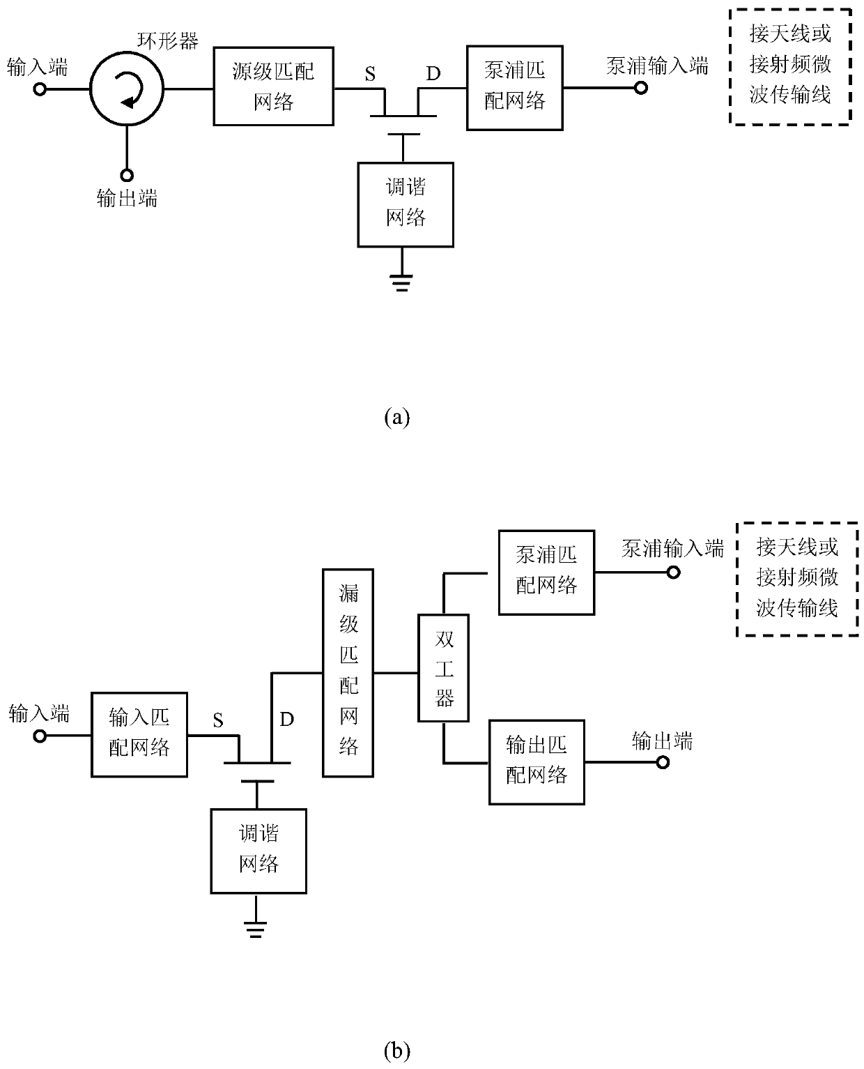
[0023] Such as image 3 Shown in (a), is the reflective microwave amplifier schematic diagram of the present invention; Comprise circulator, source matching network, pumping matching network, contain the transistor of heterojunction and tuning network; Wherein, described circulator and input end, The output terminal is connected to the input terminal of the source matching network, the output terminal of the source matching network is connected to the source of the transistor containing the heterojunction, the gate of the transistor containing the heterojunction is grounded through the tuning network, and the pump matching network is connected to the source of the transistor containing the heterojunction. The drain of the junction transistor is co...


PUM


Abstract

The invention discloses a microwave amplifier and an implementation method thereof, and belongs to the technical field of quantum mechanics, semiconductor physics and electronics. Polarization exciters in a transistor containing a heterojunction are excited to a high-energy level through pumping microwaves, and the polarization exciters excited to the high-energy level are downwards transitioned to a specified energy level in an energy level region by utilizing a chain effect of an input signal in an energy level transition process, so that amplification of input signal power is realized. Theproblems of crosstalk of a bias circuit of the direct-current bias amplifier, high circuit wiring requirement, severe direct-current voltage ripple interference and pulse amplifier working environmentrequirement, large size, complex process, high cost and the like are effectively solved; the microwave amplifier is realized by adopting a transistor manufactured by adopting a general semiconductorprocess, the amplifier is simple in structure and low in working temperature requirement, the pumping power can be provided in a space radiation form, and the microwave amplifier has very good flexibility.

Description

technical field [0001] The invention belongs to the technical fields of quantum mechanics, semiconductor physics and electronics, and in particular relates to a microwave amplifier and a realization method thereof. Background technique [0002] The amplifier is a basic device in electronics, and its main function is to amplify the power of the excitation signal and output it. Generally speaking, RF and microwave amplifiers are mostly implemented by transistors. This type of amplifier needs to introduce direct current. The purpose is to bias the transistor in the amplification area. From the perspective of energy, it converts direct current energy into microwave energy. It often causes crosstalk between devices and between modules, and it is difficult to remove this kind of crosstalk. At the same time, due to certain fluctuations in the direct current, this will introduce additional noise. Where noise performance is critical, transistor amplifiers operating at very low tempe...

Claims


Application Information

Patent Timeline
Patent Type & Authority Applications(China)
IPC IPC(8): H03F1/26H03F1/30H03F1/56
CPCH03F1/26H03F1/306H03F1/301H03F1/302H03F1/56Y02D30/70
Inventor 补世荣符阳曾成陈柳王占平宁俊松
Owner UNIV OF ELECTRONICS SCI & TECH OF CHINA
Learn More