Optical fiber liquid level sensor and optical fiber liquid level sensing method

A technology of liquid level sensor and optical fiber, which is applied in the directions of liquid level indicators, instruments, machines/engines, etc. It can solve the problems of safety considerations such as the application restrictions of electric measuring devices, and achieve the effect of low cost and adjustable range

Inactive Publication Date: 2019-09-20
NANCHANG HANGKONG UNIVERSITY
View PDF5 Cites 5 Cited by
  • Summary
  • Abstract
  • Description
  • Claims
  • Application Information

AI Technical Summary

Problems solved by technology

However, in flammable gas environments, such as oil depots, the application of electrical measuring devices is limited based on safety considerations; electrical devices usually need to consider more electromagnetic interference and electromagnetic shielding issues

Method used


Image

  • Optical fiber liquid level sensor and optical fiber liquid level sensing method
  • Optical fiber liquid level sensor and optical fiber liquid level sensing method

Examples


Embodiment 1

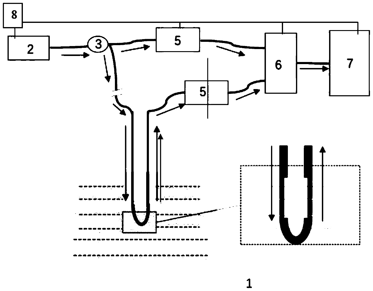
[0018] Such as figure 1 As shown, the arrow indicates the transmission direction of light or electrical signal, the present invention is realized in this way, it comprises a U-shaped optical fiber probe 1 that has been removed part of the cladding and is immersed in the liquid, and a monochromatic light source 2, Y Type optical coupling beam splitter 3, two photoelectric converters 5 for proportional detection, signal conditioning circuit 6, output and display module 7. The light that light source 2 outputs is coupled to Y-type optical coupling beam splitter 3, and one connects photoelectric converter 5 after the power ratio beam by 50:50, and the measured optical power is I 0 ; The other is connected to the input end of fiber optic probe 1. The U-shaped bending part of the fiber optic probe 1 has been uniformly and continuously removed part of the fiber cladding, and light will leak outward when it is transmitted to the fiber part where the cladding is removed. The U-shaped ...

Embodiment 2

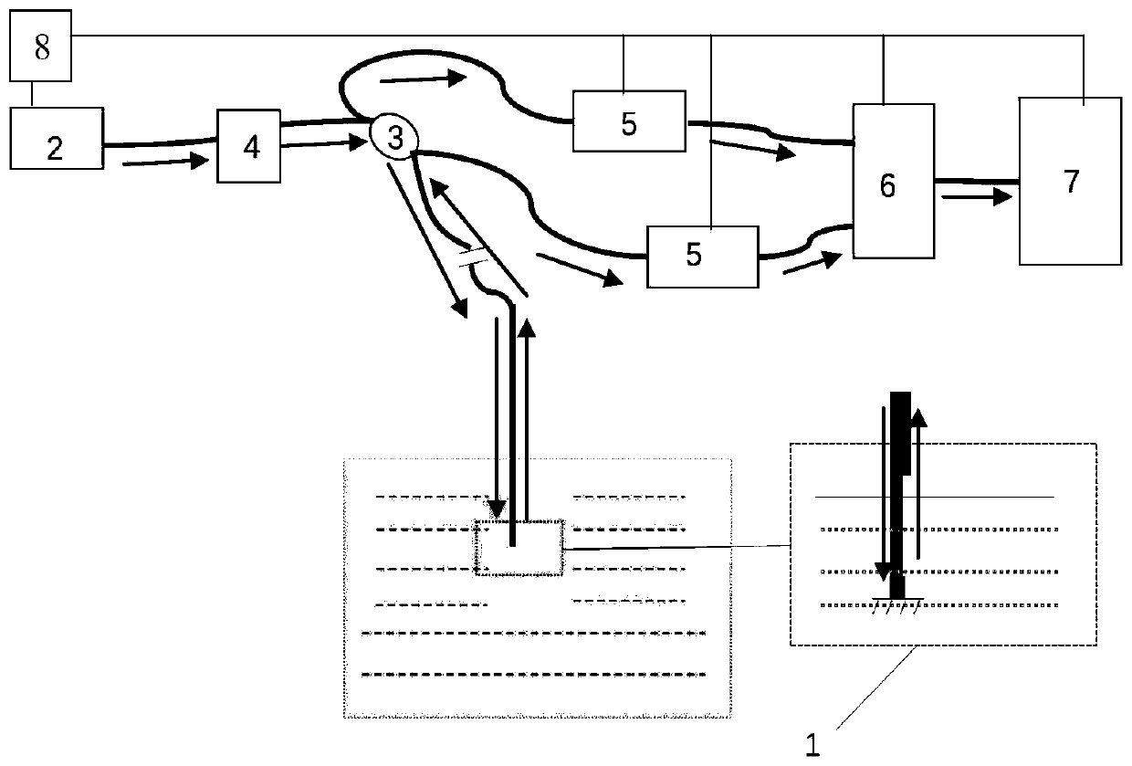
[0021] Such as figure 2 As shown, the arrow indicates the transmission direction of light or electrical signals. The device of the present invention includes an optical fiber probe 1 that has been removed part of the cladding near the end face and is submerged in the liquid upright at one end, and a monochromatic light source 2, 2 ×2 type optical coupling beam splitter 3, optical isolator 4, two photoelectric converters 5 for proportional detection, signal conditioning circuit 6, output and display module 7. The light output by the light source 2 is connected to one of the input ends of the optical coupling beam splitter 3 after the optical isolator 4, and the output end of the beam splitter is connected to the photoelectric converter 5, and the measured optical power is I 0 ; The other output end is connected to one end of fiber optic probe 1. The other end of the optical fiber probe 1 is evenly and continuously removed part of the fiber cladding, and a reflector is pasted ...


PUM


Abstract

The invention relates to an optical fiber liquid level sensor and an optical fiber liquid level sensing method. The optical fiber device is mainly illustrated to measure the liquid level by adopting the light leakage proportion in a cladding-removed optical fiber, and comprises an optical fiber probe with removed part of cladding, a monochromatic source, an optical coupling beam splitter, an optical isolator, two photoelectric converters for proportion detection, and a signal conditioning circuit. The cladding of the optical fiber probe is removed continuously or at multiple points at the end portion of the middle portion to change the sensitivity, the signal to noise ratio, and the continuity or switching characteristics of the output signal of the device. The optical fiber liquid level sensor and the optical fiber liquid level sensing method have the advantages of the intrinsic safety, the electromagnetic immunity, the adjustable measuring range, the stability, the reliability, the low cost and the like.

Description

technical field [0001] The invention belongs to the technical field of optical fiber sensing, and more specifically relates to an optical fiber liquid level sensor and a sensing method. Background technique [0002] The liquid level sensor in automatic detection is mainly based on the principle of electricity or photoelectric combination. The common technology is to partially fill the liquid between the two plates of a capacitor to the height of the liquid level. Based on the difference in the dielectric constant of liquid and air, this can There is a linear relationship between the variable capacitance value and the liquid level. However, in a flammable gas environment, such as an oil depot, the application of electrical measuring devices is limited based on safety considerations; electrical devices usually also need to consider more electromagnetic interference and electromagnetic shielding issues. Optical liquid level sensing methods can effectively avoid these limitatio...

Claims


Application Information

Patent Timeline
Patent Type & Authority Applications(China)
IPC IPC(8): G01F23/292
CPCG01F23/292
Inventor 张巍巍程浩万璐王嘉豪张志敏龚勇清史久林何兴道
Owner NANCHANG HANGKONG UNIVERSITY
Why Eureka
Try Eureka