Digital pathologic imaging device

An imaging device and digital image technology, applied in the field of optical imaging, can solve the problems of increased missed and misdiagnosed pathological diagnosis, increased numerical aperture, large size of microscope objective, etc., to achieve high-quality clear imaging, increase path length, spectrum Evenly distributed effect

Pending Publication Date: 2019-09-20
DAKEWE SHENZHEN MEDICAL EQUIP CO LTD
View PDF0 Cites 3 Cited by
  • Summary
  • Abstract
  • Description
  • Claims
  • Application Information

AI Technical Summary

Problems solved by technology

However, according to the above-mentioned relationship between the parameters that determine the performance of the microscope objective lens, it can be known that the clear imaging of the ultra-microstructure must increase the numerical aperture and magnification, which will inevitably lead to the reduction of the field of view and the increase in the number of intermediate lenses. The size of the objective lens and the production cost and assembly difficulty increase sharply
[0007] The above-mentioned limitations in the traditional microscope objective lead to many invariants for optical microscope users in practical applications.
For example, in the field of pathological diagnosis, doctors have to undertake the task of microscopic observation of more than 100 pathological slices every day. Using traditional microscope objectives, due to the limitation of numerical aperture and magnification, doctors need to switch repeatedly when observing each slice. Microscopic objective lens with high magnification to achieve accurate observation of pathological slices from macroscopic to ultramicrostructure to ensure the accuracy of pathological diagnosis; Observation and diagnosis of each local tissue in the entire section to prevent misdiagnosis and missed diagnosis; the above-mentioned limitations in the performance of traditional microscopes lead to increased complexity in the use of optical microscopes. It usually takes more than 20 minutes for doctors to observe a pathological section, which is extremely inefficient , in the face of a huge diagnostic workload, pathologists have a huge labor burden and intensity, which not only threatens the physical and mental health of pathologists, but also increases the risk of missed and misdiagnosed pathological diagnoses
On the other hand, due to the large size of the microscopic objective lens, the optical microscope is large in size, which is not conducive to placing a large number of it in the pathology department with limited area. Increase
[0008] Due to the defects of the above-mentioned light source system and microscope objective lens, although digital pathology technology can reduce the burden and labor intensity of pathologists to a certain extent, and improve the accuracy of pathological diagnosis, the efficiency of pathological diagnosis has not been improved, even compared with traditional methods. The efficiency of pathological diagnosis is even lower, which seriously limits the development of digital pathology technology and its clinical application

Method used


Image

  • Digital pathologic imaging device
  • Digital pathologic imaging device
  • Digital pathologic imaging device

Examples


Embodiment Construction

[0093] The following will clearly and completely describe the technical solutions in the embodiments of the present invention with reference to the drawings in the embodiments of the present invention. It should be noted that if there is a directional indication (such as up, down, left, right, front, back...) in the embodiment of the present invention, the directional indication is only used to explain the position in a certain posture (as shown in the accompanying drawing). If the specific posture changes, the directional indication will also change accordingly. In addition, if there are descriptions involving "first", "second" and so on in the embodiments of the present invention, the descriptions of "first", "second" and so on are only for descriptive purposes, and should not be interpreted as indicating or implying Its relative importance or implicitly indicates the number of technical features indicated. Thus, the features defined as "first" and "second" may explicitly o...


PUM


Abstract

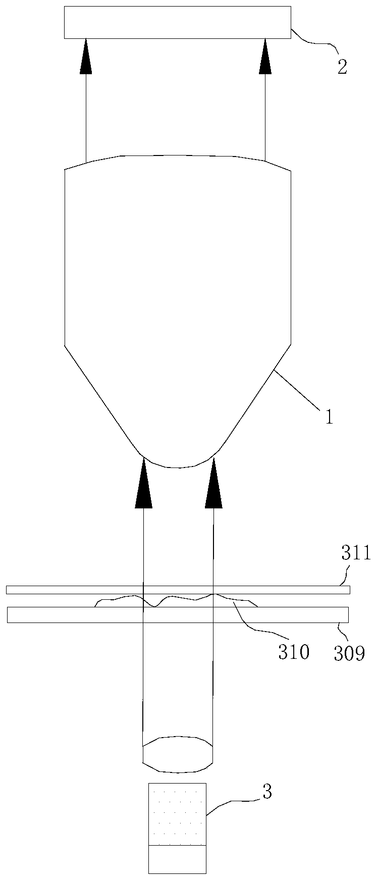
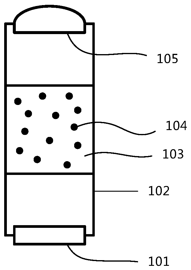
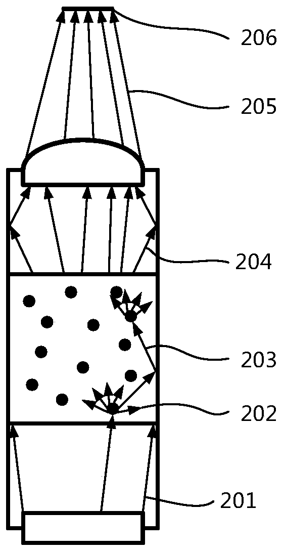
The invention relates to a digital pathologic imaging device, and belongs to the technical field of optical imaging. The digital pathologic imaging device comprises a microscopic illumination device, a microscopic object lens and a digital image sensor; the microscopic illumination device comprises a light source, a Mie scattering device, an optical cavity and a condenser; the light source is positioned in one side of the Mie scattering device, the condenser is positioned in the other side of the Mie scattering device, and the light source emits light to irradiate the Mie scattering device; the Mie scattering device is used to scatter and radiate the light from the light source onto the condenser; the condenser focuses and outputs the light input from the Mie scattering device to a tested object; the microscopic illumination device comprises first and second lenses arranged along the optical axis direction, and the first lens is used to receive light from the tested object; the front surface of the first lens and the back surface of the second lens are plated with semi-transmitting semi-reflecting optical dielectric light splitting films respectively; and the digital image sensor receives light from the second lens and carries out digital imaging.

Description

technical field [0001] The invention relates to the technical field of optical imaging, in particular to a digital pathological imaging device. Background technique [0002] Digital pathology refers to the application of computers and networks in the field of pathology, and is a technology that organically combines modern digital systems with traditional optical amplification devices. It mainly uses digital pathology imaging equipment to scan sliced ​​tissues. [0003] Existing digital pathology imaging equipment generally includes a microscope objective lens and a light source system. The light irradiated by the light source usually has a Gaussian distribution. The central area of ​​the microscopic field of view has the highest brightness, and the surrounding brightness is low. This problem of uneven illumination is reflected in the uneven illumination of digital images in digital microscopes, especially in digital pathology. In the field of full-slice imaging, digital im...

Claims


Application Information

Patent Timeline
Patent Type & Authority Applications(China)
IPC IPC(8): G02B21/06G02B21/36
CPCG02B21/06G02B21/361G02B21/365
Inventor 唐玉豪何俊峰吴庆军于綦悦韦建飞邓建刘亚鸿周雄兵王阳
Owner DAKEWE SHENZHEN MEDICAL EQUIP CO LTD
Why Eureka
Try Eureka