
Grinder

A grinding machine and oil sludge technology, which is applied in the field of oil sludge pollutant treatment machinery and equipment, can solve the problems of failure to fully realize sludge recycling and reuse, low energy utilization rate of thermal analysis method, and high treatment and disposal costs, so as to reduce blockage and strengthen Strength, wear-reducing effect

Inactive Publication Date: 2019-09-24
曾尚武
View PDF11 Cites 6 Cited by
  • Summary
  • Abstract
  • Description
  • Claims
  • Application Information

AI Technical Summary

Problems solved by technology

However, the thermal analysis method has the problems of low energy utilization rate and high unit treatment and disposal cost, and it only extracts and recovers most of the petroleum substances, and fails to fully realize the recovery and reuse of sludge
[0004] At present, grinding machine is an important processing method in processing, with high processing precision and wide range of processing materials, but there are few grinding machines dedicated to the purification process of oil sludge pollutants

Method used


Image

  • Grinder
  • Grinder
  • Grinder

Examples


Embodiment 1

[0131] The oil sludge treatment process in this embodiment is a modular oil sludge treatment system, which purifies oil sludge pollutants generated in oil and gas field production. The modular oil sludge treatment system will be described in detail below.

[0132] The modular oil sludge treatment system adopts a modular structure, and the modular structure forms the oil sludge treatment system into a three-story building structure. Figure 11 It is a schematic diagram of the building structure of the modular oil sludge treatment system. Such as Figure 11 As shown, the building adopts a cast-in-place hollow building body, including the lower, middle and upper floors, so that the construction can be simple, fast, environmentally friendly and energy-saving. The devices used to implement the specific steps of the above oil sludge treatment process are respectively arranged on the three floors.

[0133] In the lower floor, as the main processing equipment, there is a grinding ma...

Embodiment 2

[0151] The oil sludge treatment process involved in the present invention can not only be configured as the oil sludge treatment system described in Embodiment 1 above, but also can be configured as a mobile oil sludge treatment system as required. The mobile sludge treatment system installs different equipment for sludge treatment on a movable vehicle chassis, and is towed to any occasion that requires emergency response to sludge pollutants for flexible on-site operations.

[0152] The following will combine Figure 12 , 13 The structure of the mobile sludge treatment system of this embodiment will be described in detail.

[0153] The mobile sludge treatment system can be refitted with various flatbed semi-trailers, and can be towed and moved to the work site by the head 710. The mobile oil sludge processing system in this embodiment includes a vehicle frame 720 and a plurality of processing equipment arranged on the vehicle frame 720 . The frame 720 is equipped with a pl...


PUM


Abstract

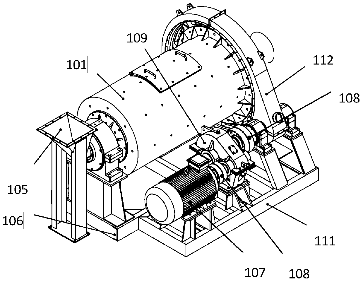
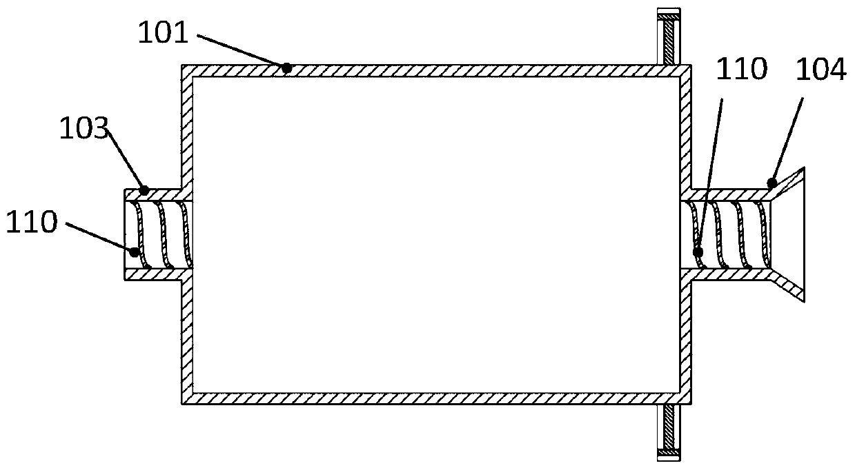
The invention provides a grinder which is used for further grinding a material formed after oil sludge pollutants are crushed before oil separation during purification treatment of the oil sludge pollutants. The grinder comprises a barrel, a host base, a driving device and a driving base, wherein a bull gear is arranged at the end part of one end of an outer wall of the barrel; a feed helical bucket and a discharge helical bucket are arranged on the circular bottom faces of the two ends of the barrel; helical structures for guiding and made of metal rod-shaped materials are arranged on the inner wall surface of at least one of the feed helical bucket and the discharge helical bucket; the feed helical bucket is connected with a feed port; the driving device comprises a motor, a coupler, a reducer and a pinion; the pinion is engaged with the bull gear of the barrel, so that rotation of the barrel driven by the motor is achieved; due to a unique helical port design, the oil sludge pollutants can be guided into the barrel, and the ground oil sludge pollutants can be guided to leave the interior of the barrel; and blocking of the helical buckets due to the oil sludge pollutants can be reduced.

Description

technical field [0001] The invention relates to the technical field of oil sludge pollutant treatment mechanical equipment, in particular to a grinder for oil sludge. Background technique [0002] Oily sludge mixed with oily water and surface soil produced in the production, transportation and refining process of oil and gas fields, tank cleaning bottom sludge, and sludge produced by oilfield sewage treatment stations are collectively referred to as oily sludge. The components of the oily sludge mainly include oil, mud, sand, etc., and are also mixed with petroleum production equipment and some domestic garbage. Its components are complex, seriously harmful to the environment, and the waste output is huge. [0003] At present, domestic and foreign oil sludge resource treatment methods are mainly thermal analysis methods. The existing thermal analysis methods are divided into direct thermal analysis and indirect thermal analysis. Direct thermal analysis basically uses hot ste...

Claims


Application Information

Patent Timeline
Patent Type & Authority Applications(China)
IPC IPC(8): B02C17/10B02C17/18B02C17/24B02C23/02
CPCB02C17/10B02C17/18B02C17/183B02C17/24B02C2201/06
Inventor 曾尚武
Owner 曾尚武
Learn More