Novel porosity gradient thermal barrier coating
A thermal barrier coating and porosity technology, applied in the coating, metal material coating process, superimposed layer plating and other directions, can solve the problems of coating peeling, stress concentration, etc. Thermal shock performance and service life, the effect of improving the thermal insulation effect
- Summary
- Abstract
- Description
- Claims
- Application Information
AI Technical Summary
Problems solved by technology
Method used
Image

Examples
Embodiment 1
[0038] The thermal barrier coating in Example 1 comprises:
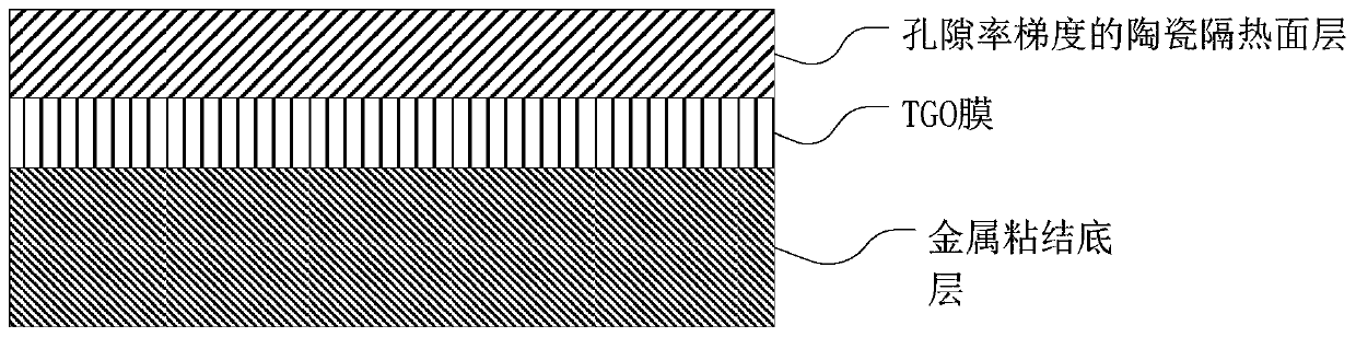
[0039] A metal bonded underlayer grown on the surface of a substrate. The thickness of the metal bond sublayer is 60 μm. The metal bond primer is made of MCrAlY powder.
[0040] A TGO layer grown on top of a metal bonded underlayer. The thickness of the TGO layer is 0.4 μm.
[0041] A ceramic insulation surface layer grown on top of the TGO layer. Ceramic insulation facings are made of zirconia partially stabilized with yttria. The porosity of the ceramic heat-insulating surface layer decreases in a continuous gradient from the interface between the TGO layer and the ceramic heat-insulating surface layer to the outer surface of the ceramic heat-insulating surface layer. The thickness of the ceramic thermal insulation surface layer is 330μm.
[0042] The sample prepared in Example 1 is defined as sample A1.
Embodiment 2
[0044] The thermal barrier coating in embodiment 2 comprises:
[0045] A metal bonded underlayer grown on the surface of a substrate. The thickness of the metal bond primer was 280 μm. The metal bond primer is made of MCrAlY powder.
[0046] A TGO layer grown on top of a metal bonded underlayer. The thickness of the TGO layer is 0.3 μm.
[0047] A ceramic insulation surface layer grown on top of the TGO layer. Ceramic insulation facings are made of yttria-stabilized zirconia. The porosity of the ceramic heat-insulating surface layer decreases in a continuous gradient from the interface between the TGO layer and the ceramic heat-insulating surface layer to the outer surface of the ceramic heat-insulating surface layer. The thickness of the ceramic thermal insulation surface layer is 450 μm.
[0048] The sample prepared in Example 2 is defined as sample A2.
Embodiment 3
[0050] The thermal barrier coating in embodiment 3 comprises:
[0051] A metal bonded underlayer grown on the surface of a substrate. The thickness of the metal bond primer was 300 μm. The metal bond primer is made of MCrAlY powder.
[0052] A TGO layer grown on top of a metal bonded underlayer. The thickness of the TGO layer is 0.7 μm.
[0053] A ceramic insulation surface layer grown on top of the TGO layer. Ceramic insulation facings are made of yttria-stabilized zirconia. The porosity of the ceramic heat-insulating surface layer decreases in a continuous gradient from the interface between the TGO layer and the ceramic heat-insulating surface layer to the outer surface of the ceramic heat-insulating surface layer. The thickness of the ceramic thermal insulation surface layer is 350 μm.
[0054] The sample prepared in Example 3 is defined as sample A3.
PUM
| Property | Measurement | Unit |
|---|---|---|
| thickness | aaaaa | aaaaa |
| thickness | aaaaa | aaaaa |
| thickness | aaaaa | aaaaa |
Abstract
Description
Claims
Application Information
 - R&D
- Intellectual Property
- Life Sciences
- Materials
- Tech Scout
- Unparalleled Data Quality
- Higher Quality Content
- 60% Fewer Hallucinations
Browse by: Latest US Patents, China's latest patents, Technical Efficacy Thesaurus, Application Domain, Technology Topic, Popular Technical Reports.
© 2025 PatSnap. All rights reserved.Legal|Privacy policy|Modern Slavery Act Transparency Statement|Sitemap|About US| Contact US: help@patsnap.com