
Front end motor-generator system and hybrid electric vehicle operating method

一种混合动力电动、电动发电机的技术,应用在混合动力车辆、电力制动系统、机动车等方向,能够解决增加车辆重量、辅助动力装置昂贵、工程困难等问题

Active Publication Date: 2019-10-01
BENDIX COMML VEHICLE SYST LLC
View PDF7 Cites 0 Cited by
  • Summary
  • Abstract
  • Description
  • Claims
  • Application Information

AI Technical Summary

Problems solved by technology

This approach adds significantly to vehicle weight, cost and wiring harness and control system line length and complexity, potentially negating any fuel economy or emissions reductions provided by removing engine accessory loads from the engine
[0008] State-of-the-art hybrid electric vehicle systems have a number of disadvantages that hinder their adoption in applications such as commercial vehicles
These include: the engineering difficulties associated with trying to scale up hybrid powertrain components to handle the very high torque output of a large engine (typically a high torque output diesel engine); the interdependence of engine and motor-generator operation, as these components are either Integral to the rear of the engine, or directly on the driveline (i.e., the engine and motor-generator must rotate together, even when rotation of one or the other is not required or even detrimental to overall vehicle operating efficiency); and when not operating "Hotel" loads cannot be met independently without the vehicle engine or operating a separate on-board auxiliary power unit ("APU") (for example, a dedicated stand-alone internal combustion engine package or a dedicated battery pack containing multiple conventional batteries and associated support equipment ( e.g. nighttime climate control and 120 volt power demand in a sleeper compartment of a commercial vehicle tractor)
These auxiliary power units are expensive (typically several thousand dollars), heavy and require considerable space on an already space-constrained vehicle
In the case of fuel burning APUs, they also have the further disadvantage of potential hazards associated with open flames and the production of carbon monoxide (which can enter the sleeper compartment during driver rest periods), and in the case of all-electric APUs, they also have A further disadvantage that the vehicle's engine may not return sufficient energy for extended periods of time to meet all of the vehicle's accessory needs when the vehicle's engine is off

Method used


Image

  • Front end motor-generator system and hybrid electric vehicle operating method
  • Front end motor-generator system and hybrid electric vehicle operating method
  • Front end motor-generator system and hybrid electric vehicle operating method

Examples


Embodiment Construction

[0086] Front end motor generator system embodiment.

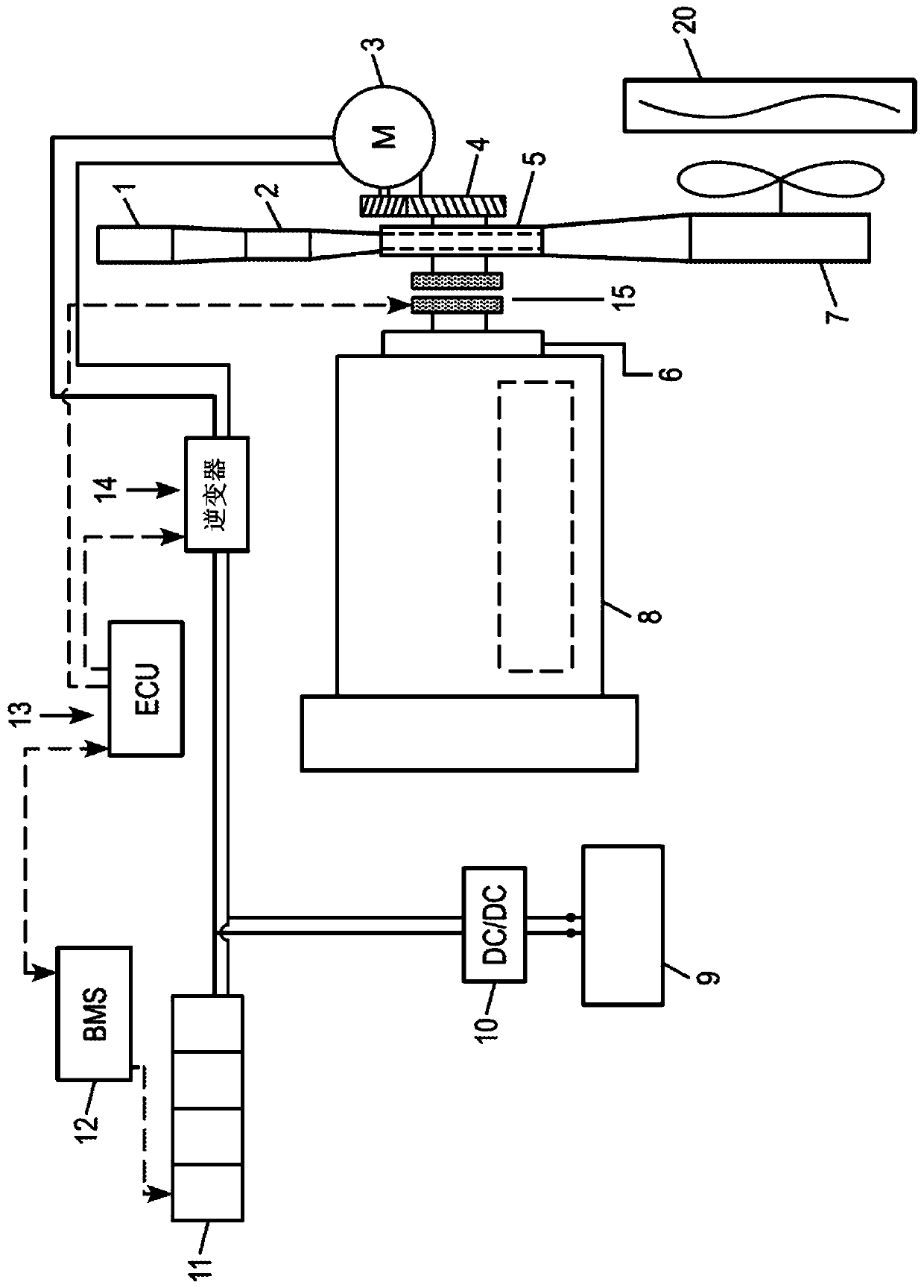
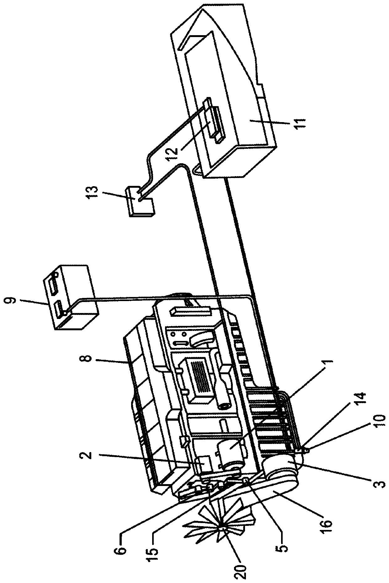
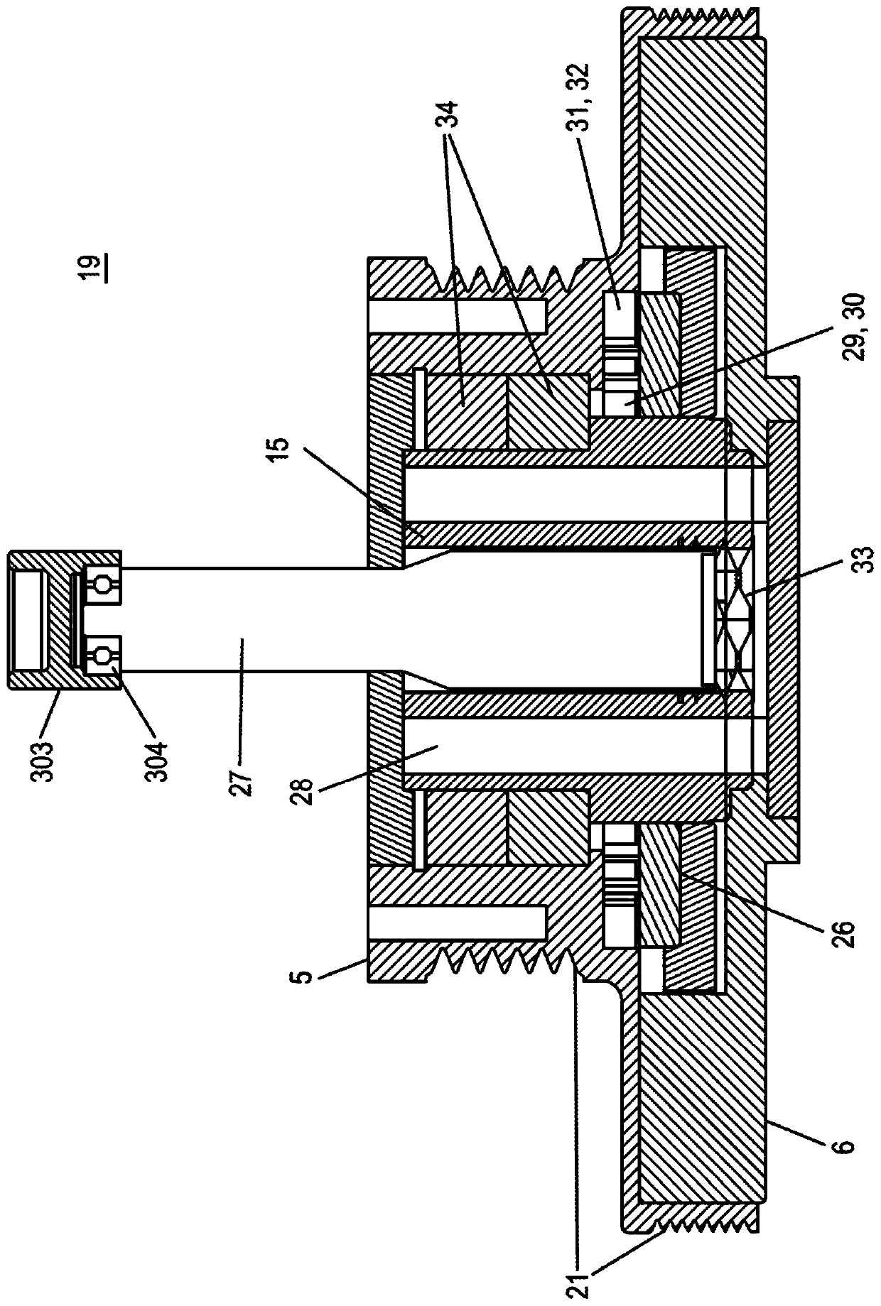
[0087] Figure 1A is a schematic diagram illustrating components of an embodiment of a FEMG system according to the present invention. Figure 1B is a schematic diagram of several FEMG system components in a commercial vehicle chassis. In this arrangement, the engine accessories (comprising the air compressor 1 , the air conditioner compressor 2 and the engine cooling fan 7 arranged to pull cooling air through the engine coolant radiator 20 ) are belt driven by the pulley 5 . The pulley 5 is positioned coaxially with the damper 6 , which is directly coupled to the crankshaft of the internal combustion engine 8 . The accessories can be directly driven by the belt or provided with their own on / off or variable speed clutch (not shown) which allows a separately clutched accessory to be partially or completely disengaged from the belt drive.

[0088] In addition to driving the accessory drive belt, pulley 5 is also coupled to ...


PUM


Abstract

A system and method are provided for hybrid electric internal combustion engine applications in which a motor-generator, a narrow switchable coupling and a torque transfer unit therebetween are arranged and positioned in the constrained environment at the front of an engine in applications such as commercial vehicles, off-road vehicles and stationary engine installations. The motor-generator is preferably positioned laterally offset from the switchable coupling, which is co-axially-arranged with the front end of the engine crankshaft. The switchable coupling is an integrated unit in which a crankshaft vibration damper, an engine accessory drive pulley and a disengageable clutch overlap such that the axial depth of the clutch-pulley-damper unit is nearly the same as a conventional belt drive pulley and engine damper. The front end motor-generator system includes an electrical energy store that receives electrical energy generated by the motor-generator when the coupling is engaged. Whenthe coupling is disengaged, the motor-generator may drive the pulley portion of the clutch-pulley-damper to drive the engine accessories using energy returned from the energy store, independent of the engine crankshaft.

Description

[0001] This application claims priority to US Application No. 15 / 378,764, filed December 14, 2016, the disclosure of which is incorporated herein by reference in its entirety. technical field [0002] The present invention relates to hybrid electric vehicles, and more particularly to a system for selectively coupling a hybrid power generation and storage system with an internal combustion engine. The invention also relates to a method of operating the system. Background technique [0003] Hybrid electric vehicles having an internal combustion engine combined with a motor-generator and an electrical energy storage system have become the focus of considerable interest in the automotive field, especially in the passenger car field. The development of hybrid electric vehicle systems has only recently begun to generate significant interest in commercial and off-road vehicles (e.g., trucks and buses in vehicle classes 2-8), earth-moving equipment, and railway applications, as well...

Claims


Application Information

Patent Timeline
Patent Type & Authority Applications(China)
IPC IPC(8): B60K6/22B60K6/20B60K6/26B60K6/48B60K6/485B60L50/16
CPCB60K6/448B60K2006/4825B60W20/20B60L7/22B60L15/2054B60L2210/10B60L2210/42B60L2240/421B60L2240/423B60L2240/441B60L2240/443B60L50/15B60L50/16B60L50/30B60L58/22B60L58/20B60W2710/021B60L2240/507Y10S903/946Y10S903/951B60L58/15Y02T10/62Y02T10/64Y02T10/72Y02T10/70Y02T10/7072B60K2006/4833B60K6/48B60Y2300/91B60Y2400/112B60Y2400/421
Inventor 大卫·科拉纹森佐费尔南多·贝内加斯·迪亚斯
Owner BENDIX COMML VEHICLE SYST LLC
Learn More