Tank type shock wave treatment handle and equipment

A treatment handle and treatment equipment technology, which is applied in physical therapy, vibration massage, massage auxiliary products, etc., can solve the problems of long duration, reduced treatment effect, and great physical requirements for doctors, and achieves good adaptability and increased distance. , the effect of improving the effect

Active Publication Date: 2019-10-08
李卫
View PDF18 Cites 3 Cited by
  • Summary
  • Abstract
  • Description
  • Claims
  • Application Information

AI Technical Summary

Problems solved by technology

[0004] Acoustic shock waves for extracorporeal shock wave therapy can be obtained by various methods, such as electrohydraulic, electromagnetic and ballistic shock waves, etc.; when performing extracorporeal shock wave therapy, such as shoulder periarthritis, humeral epicondylitis, Achilles tendinitis and other diseases, need The doctor holds the shock wave generator and adjusts the angle and position of the handle according to the patient's condition based on his experience. According to the doctor's experience, the angle and position of the handle during the treatment process has better treatment pertinence. Targeted treatment obtained from experience can achieve better results, so that the treatment operation is not universal to a certain extent, and one treatment requires the doctor to repeat the same control handle operation many times, which lasts for a long time, and it is inconvenient to hold the treatment for a long time. It requires a lot of physical strength for doctors, and at the same time, it is easy to reduce the treatment effect due to fatigue

Method used


Image

  • Tank type shock wave treatment handle and equipment
  • Tank type shock wave treatment handle and equipment
  • Tank type shock wave treatment handle and equipment

Examples


specific Embodiment approach 1

[0044] A pot type shock wave therapy handle disclosed in this embodiment, combined with figure 1 shown, specifically;

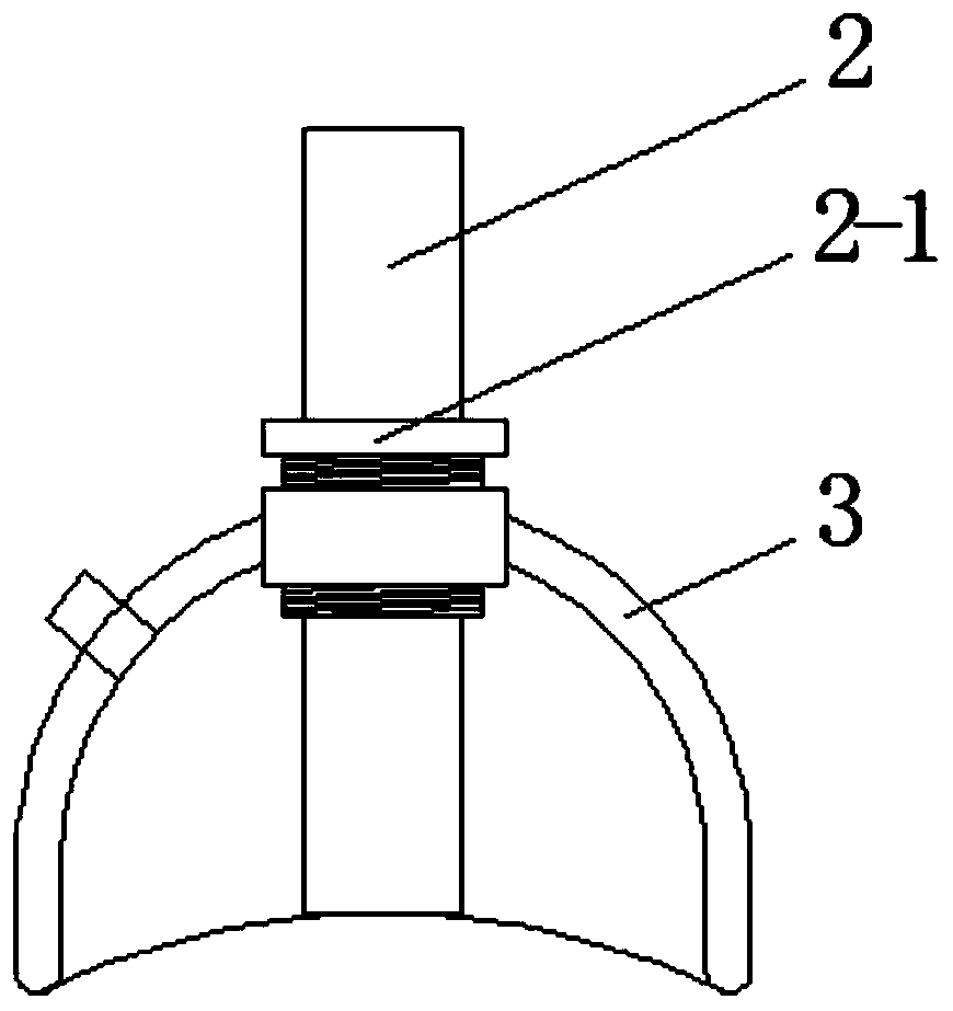
[0045] Comprising a treatment head 2 capable of coupling impact energy and generating shock waves, the lower end of the treatment head 2 is provided with a tank body 3, the upper end of the tank body 3 is connected with the treatment head 2, and the lower end of the tank body 3 is provided with an adsorption opening, so After the tank body 3 is drawn out of the internal air, the treatment head 2 is fixed on the body surface to be treated which is attached to it;

[0046] The treatment head 2 of this embodiment adopts a ballistic shock wave system. The inside of the treatment head 2 is provided with a projectile trajectory, and the projectile is slidably arranged in the projectile trajectory. Under the push of the high-pressure gas, the projectile can accelerate and hit the end of the treatment head to generate a treatment shock wave. , or the projectile is pus...

specific Embodiment approach 2

[0051] This embodiment is based on the specific implementation mode 1, specifically, in combination with figure 2 As shown, the tank body 3 is coaxially arranged with the treatment head 2, and the treatment head 2 passes through the tank body 3 from the upper end, so that the tank body 3 is coated on the outside of the treatment head 2;

[0052] The tank body 3 includes: an outer tank layer 3-1 and an inner tank layer 3-2, the outer tank layer 3-1 is covered outside the inner tank layer 3-2, so that the outer tank layer 3-1 and the inner tank layer A cavity is formed between 3-2, the upper end of the cavity is sealed, and the lower end forms an adsorption opening;

[0053] The cavity is in the shape of a cylinder or an inverted bowl, the top of the cavity is sealed, and the bottom forms a ring-shaped adsorption opening. The end of the treatment head 2 is located inside the inner tank layer 3-2, and the connection hole for vacuuming is set on the outer tank layer 3 -1, commun...

specific Embodiment approach 3

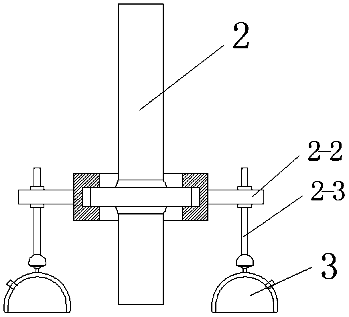
[0056] This embodiment is based on the specific implementation mode 1, specifically, in combination with image 3 As shown, several tank bodies 3 are arranged on the outside of the treatment head 2, so that the treatment head 2 has a plurality of fixed points on the body surface to be treated that are attached to it;

[0057] In the present embodiment, the outer side of the treatment head 2 is provided with several fixed rods 2-2 arranged in the radial direction, and each fixed rod 2-2 is provided with a tank body 3, and the upper end of the tank body 3 is connected with a ball hinge. One end of the telescopic rod 2-3 is connected, and the other end of the telescopic rod 2-3 is connected with the fixed rod 2-2;

[0058] During treatment, the doctor judges the treatment area based on experience, and adjusts the angle of the tank body 3 and the length of the telescopic rod 2-3 in turn according to the surface shape of the treatment area, so that the adsorption opening of the tan...


PUM


Abstract

The invention belongs to the technical field of shock wave treatment, in particular to a tank type shock wave treatment handle and equipment. The tank type shock wave treatment handle comprises a treatment head which can couple shock energy and generate shock waves and is characterized in that a tank is arranged at the lower end of the treatment head, the upper end of the tank is connected with the treatment head, the lower end of the tank is provided with a sucking opening, and the treatment head can be fixed to an to-be-treated body surface after the air inside the tank is extracted. The tank type shock wave treatment handle has the advantages that to-be-treated body surface area moves towards the interior of the tank under the effect of atmospheric pressure to allow the tank to be fixedto the body surface after the air inside the tank is extracted, and accordingly the treatment head connected with the tank is fixed to the body surface to achieve automatic treatment; meanwhile, during shock wave treatment, the tank has effects of dredging the channels, removing stasis, promoting qi and blood circulation and relieving swelling and pain on the to-be-treated body surface area, andthe shock wave treatment effect is increased.

Description

technical field [0001] The invention belongs to the technical field of shock wave therapy, and in particular relates to a pot-type shock wave therapy handle and equipment. Background technique [0002] Shock wave therapy is a sound wave with mechanical properties generated by the compression of the medium. During the transmission process, the shock wave will cause the physical properties of the medium such as pressure, temperature, and density to change. Shock waves are applied to the body surface, and the shock waves pass through the skin to treat internal tissues. , has the advantages of non-surgical and non-invasive; [0003] Since the 1970s and 1980s, people have applied shock waves to the clinical treatment of urinary calculi. As the shock wave energy stimulates bone growth, angiogenesis, chronic orthopedic healing, bone healing, wound healing, and vascular reconstruction, etc. are gradually being used. Invention, and gradually derived extracorporeal shock wave therapy...

Claims


Application Information

Patent Timeline
Patent Type & Authority Applications(China)
IPC IPC(8): A61H23/00
CPCA61H23/008A61H2201/0153
Inventor 李卫邢更彦张守相李艳奇宋达疆刘锐于思骄卫霖张文龙叶义杰于淼王策
Owner 李卫
Why Eureka
Try Eureka